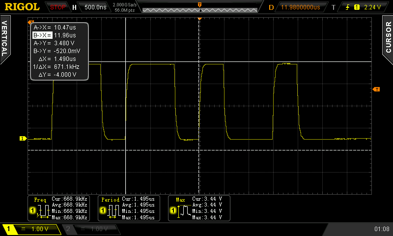
Typically bit-banging an I/O line is the common method of driving the WS2812B (WS2811) RGB LEDs. However, this ties up precious microcontroller cycles while it waits around to flip a bit. A less processor intensive method is to use one of the built-in Serial Peripheral Interface (SPI) modules. This is done using specially crafted data and baud rate settings, that when shifted out over the Serial Data Out (SDO) pin, recreate the needed WS2812B signal timing. Even when running in SPI mode, your hardware TX buffer size will limit how many pixels you can update without CPU intervention.
[Henrik] gets around this limitation by using peripheral DMA (Direct Memory Access) to the SPI module in the Microchip PIC32MX250F128B microcontroller. Once properly configured, the DMA controller will auto increment through the defined section of DMA RAM, sending the pixel data over to the SPI module. Since the DMA controller takes care of the transfer, the micro is free to do other things. This makes all of DMA memory your display buffer. And leaves plenty of precious microcontroller cycles available to calculate what patterns you want the RGB LEDs to display.
Source code is available at the above link for those who would like to peruse, or try it out. This is part of [Henrik’s] Pixel Art Project. Video of DMA based SPI pixels after the break:
For more DMA based WS2812B Pixels, check out a this PWM based version.


I’m not trying to be a a**hole, but isn’t DMA use a commodity by now (I mean, on cpus that has DMA) ?
Yes, but keep in mind that the Arduino-based crowd has to relearn all of these concepts from scratch, since they ignore the AVR architecture entirely in favor of C/C++ libraries.
Reminds me of the old saying, “Those who do not understand UNIX are doomed to reinvent it, poorly.”
8bit AVRs have DMA? Or did Arduino move up to the 32bit AVRs?
I believe the Atmel 8-bit Xmega series have DMA, but not the 8-bit mega as are used in the 8-bit Arduino’s. I think the ARM based Arduino’s do have it also, but AFAIK it is not exposed by the libraries.
Normal 8 bit AVR, no. But Hack-a-Day has numerous times covered my DMA-based OctoWS2811 library, which works with the Arduino software and Arduino sketches, and lots of awesome large-scale LED projects using OctoWS2811.
This isn’t an add or plug, and I won’t want to detract from this story any more, by mentioning specific hardware. You can pretty easily find the details with a google search, if you’re inclined.
Using DMA can be tricky on bare metal microcontroller programming. It’s pretty awesome to see more people doing it.
When I read the Headline I immediately thought this was about [Paul] and his OctoWS2811 Library, and I thought HaD got it wrong since [Paul] doesn’t use SPI. But although I was wrong myself I think [Paul] should at least be mentioned in this Article, since he started the whole DMA-based-LED-driving thing.
I took a somewhat different approach with my clock project here:
https://learn.adafruit.com/madisons-neoclock-a-pic-kicad-neopixel-adventure
I’ve wanted to move away from bit-banging in favor of more hardware support while still using a small (PIC16F1847) device. With the ‘1847 I’m using the EUSART as a synchronous slave to drive the dual PWM+DSM producing the bitstream for the NeoPixels. The internal RAM in the PIC contains the 3-byte color values which are retrieved via SPI (the PIC is the SPI Master) from a renderer. (The expectation is the SPI Slave in the renderer would use DMA to provide the color-byte frame whenever the PIC initiated the SPI exchange.)
All that gives me slightly faster than 50 Hz update rate for 256 NeoPixels – not too bad for a single PIC.
Speaking of PICs, there’s a Microchip appnote describing how to use the configurable logic cell (CLC) to generate a WS2811 compatible signal.
Some of the newer low- and midrange PIC micros have one or more CLCs.
Besides the practical use, this is a nice example of what you can do with them.
On mobile so I didn’t get a clean URL but it’s AN1606
neat http://ww1.microchip.com/downloads/en/AppNotes/00001606A.pdf
has anyone user a cypress PSOC for it ?
That’s pretty interesting! Like a miniature FPGA :) Hope to see in the 32 bit series
Must have hit the wrong button. This was in response to cyk
if anyone is interested this is covered in “Programming 32-bit Microcontrollers in C: Exploring the Pic32”
http://books.google.com/books/about/Programming_32_bit_Microcontrollers_in_C.html?id=PTcNpClUH1QC
Henrik is a super nice guy. He is very helpful to anyone with PIC problems, I pick his brain often.
Also, AVR / ardunio users need to STFU, PICs have been around way longer and everything you see done on an AVR or ardunio has been done 100 times over on other micros for years, so he doesn’t need to credit anyone with anything.
This is good idea with DMA+spi,i even using program delay of debug code to handle the ws2812B led strip(http://www.ledlightmake.com/rgb-addressable-led-strip-c-80_87/led-ws2812b-addressable-digital-stripsmd5050-strips-60-pcsm-p-216.html) .the test code as follows:
#asm
MOV P1, #1
nop
nop
nop
nop
nop
nop
nop
nop
nop
nop
nop
nop
nop
nop
nop
nop
nop
nop
nop
nop
nop
nop
nop
nop
nop
nop
nop
nop
nop
nop
nop
nop
nop
nop
nop
nop
nop
nop
nop
MOV P1, #0
nop
nop
nop
nop
nop
nop
nop
nop
nop
nop
nop
nop
nop
nop
nop
nop
nop
nop
nop
nop
nop
nop
nop
nop
nop
nop
nop
nop
nop
ENDASM
Does anyone have the original PIC32 code referred to in the article (link no longer works), as I am trying to program a PIC32 as an E1.31 to WS2811 bridge. Thanks!
Stop looking – found it on github: https://github.com/hthulin/WS2811/blob/master/main.cpp
Hope this helps someone else :)