The last few years have seen great strides in budget printed circuit board manufacturing. These days you can have boards made in a week for only a few dollars a square inch. Flexible PCBs still tend to be rather expensive though. [Mikey77] is changing that by making flex circuits at home with his 3D printer. [Mikey77] utilized one of the properties of Ninjaflex Thermoplastic Elastomer (TPE) filament – it sticks to bare copper!
The TPE filament acts as an etch resist, similar to methods using laser printer toner. For a substrate, [Mikey77] lists 3 options:
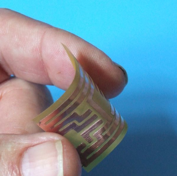
.004″ thick “Scissor cut” copper clad board from Electronics Goldmine
.002″ thick pure copper polyester taffeta fabric from lessEMF.com
<.001″ Pyralux material from Adafruit, which is one of the materials used to make professional flex PCBs.
A bit of spray adhesive will hold the Flex PCB down on the printer’s bed. The only issue is convincing the printer to print a few thousandths of an inch higher than the actual bed level. Rather than change the home position on his Z axis, [Mikey77] used AutoDesk 123D to create 3D PCB designs. Each of his .stl files has a “spacer bar”, which sits at the bed level. The actual tracks to be printed are in the air a few thousandths of an inch above the bed – exactly the thickness of the substrate material. The printer prints the spacer bar on the bed, then raises its Z height and prints on the flexible PCB material. We’re sure that forcing the printer to print in mid-air like this would cause some printer software to throw errors, but the system worked for [Mikey77] and his Makerbot.
Once the designs have been printed, the boards are etched with standard etching solutions such as ferric chloride. Be careful though – these thin substrates can etch much faster than regular PCB.


It’s no longer flexible when you solder parts to it.
I was thinking the same thing, and that I was going to comment “Now, make flexible components”. But then flexible circuits are not limited to being “flexed” all the time. It can be designed as such so the the circuit can be bent and molded on to an un-even surface just like how camera circuits are today. If you try to pry apart a modern camera you will see the circuit board shaped on the insides of the camera so that the parts are well cramped inside.
If that were true, then the flexible LED strips all over Ebay and such shouldn’t be flexible, because there are LEDs soldered to them.
As long as there are spaces between components, that extend unbroken from one side of the PCB to the other, the PCB can still flex in those spaces. Keeping it flexible is just a matter of planning in those spaces.
Winning
Toner tranfer would probably work pretty good with those materials too[for us no 3d printer having folk]
Not only would it work, it’d work better and with higher resolution.
Can’t iron the metal coated fabrics so toner transfer is out for them.
Why not? People iron metal-coated rigid PCB material all the time.
That technique is not restricted to just flex PCB, so the OP is misleading.
On the other hand, it might be possible to print the thin PCB as if it were a piece of paper in a laser printer.
I don’t think that would work. Printers that use toner use an electrostatic charge to transfer the toner to the paper. A copper clad board would spread the charge all over, so you wouldn’t be able to print on it.
Actually, it is possible to print on conductive substrates. I’ve personally been able to laser print on aluminum foil using a Dell B1160.
Very cool. I will have to try that. Then you could print on copper foil, glue to a substrate, and etch it.
It’s been done before and featured on this site.
The laser printer charges the drum, not the paper, so conductive paper should work.
But with this method even if it becomes stiff with solder paste, you could conceivably make you own multilayer boards with this method.
Bottom copper
Ninjaflex
layer 2 ( some way to align it to layer 1)
etch layer 2 and possibly bottom layer
Ninjaflex
align layer 3
coat bottom layer to protect
etch layer 3
Some other protect steps may need to be added and the edges of each ninjaflex layer may need to be sealed but its an idea that could prove less expensive then the standard $5/sq.in for a double sided board.
If you’re paying $5/sq in for double sided boards(and aren’t in a big hurry), you need to check out dfrobot, seeed studios, and/or OSH Park
RobotGrrl has been working on doing this too with some success including working flexible circuits
Yea! Thx for the shoutout zuul! :) The fun is just beginning.
Not too hard to print above the bed using slic3r.Just adjust the z level offset in the settings.
That’s exactly what I was thinking.
If the ninjaflex that sticks to copper is being printed as an etch resist, how do you get it off the copper after the board is etched?
Acetone.
Has anyone ever tried doing this sort of thing with Kapton?
I worked in a plating shop many years ago that did flex circuits on Kapton, and the stuff is awesome for that application. I’m just curious if anyone has tried doing a similar thing as a DIY project.
“Kapton”-based PCB is just that. The brand name material from DuPont is named “Pyralux”.
Toner for a laser printer goes well from paper to any surface without heating with acetone! Try it, it takes less than one minute of time ;)