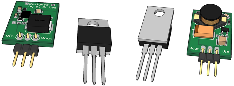
The 7805 voltage regulator is a great device if you want a simple way of bringing a voltage down to 5V. It’s a three-pin, one-component solution that puts out five volts and a lot of heat. Simple, not efficient. For his Hackaday Prize entry, [K.C. Lee] is working on a much more efficient drop-in replacement for the 7805.
Linear regulators like the 7805 are great, but they’re not terribly efficient. Depending on the input voltage you might see 50% efficiency. Going to a switch mode supply, that efficiency shoot up to about 90%.
For his drop-in replacement, [K.C. Lee] is using the LM3485, a switch mode regulator that only needs a few extra parts to turn it into a replacement for the 7805. You will need a cap on the input, but you should already be putting those in your circuit anyway, right?


So linear regulators are efficient now? (Grammar error in write up) otherwise, great concept, but already commercially available in the same form factor.
Question is: How functional is it?
I designed something similar last year that not only can operate to a given voltage, it is also current limited, therefore can be used to drive LED’s or charge batteries of all sorts (Li-Ion, NIMH, etc).
This version is particularly large, but I have a smaller one using only SMD components.
[IMG]http://i65.tinypic.com/25frtbq.jpg[/IMG]
[IMG]http://i64.tinypic.com/13zb98n.jpg[/IMG]
Simple, not efficient. -> Simple (solution), but it is not efficient.
He who makes a true (no additional components) switching replacement for the 7805 we all love deserves a Nobel prize. Mind you they give those out pretty freely these days.
I’d rather get the zobel prize – as soon as my speakers stop oscillating, that is ;)
Nice one:) When I was a kid all my diy amps would have got the igzobel prize for being squealing oscillators. This topic alone would deserve an entire article.
look up the 7805SR-H
I’m not trying to be “that guy” but hasn’t this been around for a while? Just googling 7805 drop in switching mode converter spits out quite a few commercial pieces. No sense reinventing the wheel
Yeah, they definitely exist. I’ve even seen models that don’t take up any more overall volume than a TO-220 package. Cool idea to build one yourself, but this isn’t solving any major issues.
one of those:
http://tehnikservice.net/blog/wp-content/uploads/2011/02/step-down-34063-03.jpg
For instance: http://www.ezsbc.com/index.php/featured-products-list-home-page/psu2-5.html
They’ve also got a 3.3V output version.
I made them back in 2008 specifically for my UPS project (also on hackaday.io). I have a few other types (boost, isolated) that I am going to document too that I used for my UPS.
I also wanted the module to have header pins to mate to the DIN connector as they needed to be pluggable. The same design was also used for 12V module. The input has to be as high as 18V, but when the battery runs low, I want the duty cycle to reach 100% and the PMOS to be in drop out mode for my application. Some chip with integrated NMOS switches might limit the duty cycle to be 90 or 95% that as they need the charge pump running. etc.
I had sample trays of preproduction TI/Power Trends parts (unfortunately 5V inputs parts), so I am well aware of them. I built mine with the parts I had on hand or recycled parts i.e. $0 purchased. Most of my older personal projects had budgets like that. I have decided to share, but not necessarily sell them.
It is more an awareness of the usual “just use a 78xx” from the 1970’s that most people do without thinking of how inefficient they could be. I don’t make proof of concept wonder drug to cure cancers or magical food replicators to save world hunger. Only doing my part for more engineering and designs.
Yup, many drop in replacements exist already:
http://news.ezsbc.com/wp-content/uploads/2013/02/PSU2-016CropS.jpg
http://d1gsvnjtkwr6dd.cloudfront.net/large/SC-VR-S7805_LRG.jpg
http://site.gravitech.us/MicroResearch/PowerSupplies/SWITCHING-3TERM-5V/SWITCHING-3TERM-5V_4.jpg
Second paragraph : terribly *inefficent*, not efficient.
Nice hack.
Drop-in replacements for 7805 (and for other voltages too) are also commercially available in optimized custom packages.
Look at the Okami line from Murata for example.
I’ll second the Okami line. Great product, and hard to beat the price of $6 a piece. I’ve used these to power sensitive video circuits in ROVs with no more filtering than I would use with a linear regulator, and they do a great job. Up to 36V input, to, I believe.
Thanks for the tip guys! top notch.
Already beaten price! Check Recom R-78Exx modules below:
http://www.digikey.com/product-detail/en/R-78E5.0-0.5/945-1648-5-ND/2834904
I use these Recoms a lot with very good results, although I normally shell out for the R-78C series which give you more current and a wider input voltage range in the same form factor.
Drop-in switchmode replacements for the 7805 have been available for over 20 years. For example, I have a Power Trends 78SR105HC (date code 1992) in one of my projects. Another example is the Murata OKI-78SR-5/1.5-W36-C (Digikey #811-2196-5-ND).
The problem isn’t availability; it’s cost. The 7805 costs $0.50, while the Murata switchmode replacememt is $4.30. The LM3485 costs $1.68 all by itself (using Digikey prices for comparison purposes). Except for a few customers who *need* the higher efficiency to solve an overheating problem and will pay anything to get it, these switchmode replacements don’t sell, so production quantities stay low, so prices stay high.
The cheapest down-and-dirty switchmode controller chip I know of is the MC34063 ($0.60). If you’re trying hard to keep the price down, maybe it would be a better choice?
Yep, the murata parts are my favorite, I used them for years in professional projects. The price of component is actually quite high, but 7805 plus heatsink isn’t very cheap either, not counting labour for attaching heatsink to case/PCB and applying thermal grease.
Problem with the MC34063 is that it needs an external current sense resistor, those can get fairly bulky if the current is larger…but otherwise it’s a neat little IC that still is not obsolete despite it’s age…
That current sense resistor isn’t needed unless you want current limiting to prevent overload of the chip or inductor.
You can omit current sense resistor if current limiting is not necessary. I’ve seen such configuration in devices that draw less than 500mA current, instead of 0.22 or 0.33 ohm current sense resistor they just have 0 ohm jumper.
That’s silly. There’s an inherent advantage in a CC mode controller. What happens when you try to charge a large output capacitor at startup?
SMT resistors are fairly inexpensive and small. many CC controllers have built in current limiting as well, those would be a better choice overall.
you mean like this
https://www.pololu.com/blog/318/new-products-500ma-step-down-voltage-regulator-d24v5fx
or this
http://www.elektroda.pl/rtvforum/topic2144888.html
?
Well, mine are way smaller: http://hobbyelektronik.org/w/images/thumb/6/66/Minipsu_v1_foto.jpg/632px-Minipsu_v1_foto.jpg
(version 2.1 is even smaller) Ok, got to say that will only supply 0.6 amps and the efficiency is not yet optimal but hey – in most cases more efficient than a 78xx.
excellent work, which IC did you use? thanks
Recom’s R-78Exx are good replacements too, at $2.84 on Digikey in single-unit quantities.
I’ve been using these in a project, and they’re great. The datasheets say that even the external caps are largely optional. Slightly more expensive than a linear regulator, but for most projects, the extra is a tiny percentage of the overall cost.
+1
I used them too, they are great and cheap! Highly recommended!
One of the pros of linear regulators is they don’t introduce any additional noice to the output voltage. You won’t always want to go for a switcher if your project contains sensitive analog circuitry like ADCs.
Linear regulators are just less noisy than switchers. They still generate a lot of noise themselves.
Yes, linear regulators have output noise. But they also reduce the *input* noise that they see, which switching regulators don’t usually do. Their own output noise is usually coming from the bandgap reference, and several LDOs allow bypassing that, reducing the noise down to trivial levels at the expense of slower startup times.
If/when you are forced to due to real life power constraints, you pick the switching frequency outside of your ADC band. If you do care about noise reflected back to supply from a switcher, you could attenuate it with a LC filter.
You can post linear regulate the switcher or just a noisy power supply with a good low noise, high PSRR (Power Supply Rejection Ratio) with high bandwidth LDO. There are ones with 50-70dB attenuation depending of frequency range. So even a power supply with 100mV switching noise can be reduced down to 100uV. Having that and the PSRR of your ADC, that might be good enough.
If only it were that simple…
Switching supplies don’t just generate noise at a specific frequency – the transients are broadband (big current switching spikes when the FETs turn on), and so really can’t be filtered very easily. Post-regulation with an LDO helps, but it takes a lot of searching to find an LDO with 50+ dB up into the MHz region, and obviously the LDO reduces the overall efficiency.
Micrel (now owned by Microchip) makes these nice LDOs specifically designed for switching supply filtering (Ripple Blockers), which works best for low current point-of-load regulation (e.g. for an RF section) which maintain 50 dB up through 10 MHz.
Other LDOs probably would need a carefully-selected ferrite bead to attenuate the transients, as Jim Williams (… of course, what problem hasn’t he tackled?) pointed out in a Linear app note years ago:
http://cds.linear.com/docs/en/application-note/an101f.pdf
The ringing when MOSFET turns off is at the resonant frequency by the parasitic capacitance of the diode and inductor. You can design a snubber parallel to the diode to minimize the ringing frequency.
Linear Tech also made a soft switching regulator that trade off noise with efficiency to address that.
See here for the math in a snubber design: http://www.ti.com/ww/en/analog/power_management/snubber_circuit_design.html
Snubbers can reduce the ringing, but the switch spike itself is almost certainly going to stick around, unless you’ve got a pretty inefficient switcher. Even if you critically damp it, you still get a switching spike.
Fig 6. (in comparison to Fig. 5) shows the initial impulse still remaining – which of course isn’t surprising because the impulse’s frequency content is well into the MHz, whereas the resonant frequency was in the kHz – and you’re not going to be able to attenuate frequencies above ~10-100 MHz that easily. Of course it can reduce the spike considerably, but not by the 50-60+ dB that a decently implemented LDO+filter stage would.
Now, how much of an effect that spike would have is another question. It just depends on what you’re feeding.
Wow; lots of comments on this thread!
Snubbers: There’s a simplified description of snubbers at http://www.sunrise-ev.com/LeesEVs.htm#snubbers
Data sheets: “Complete” data sheets are indeed fading away; but the internet has a good memory, so they can still be found. 3-terminal regulators *do* need more parts for any real application. Input and output capacitors are just about always required. A diode from output to input is necessary if there’s any chance there will be voltage on the output when there is a capacitor but no voltage on the input.
Noise: One thing not mentioned is that these tiny switchers use unshielded inductors. They magnetically couple noise into any nearby wiring or traces. If noise is important, the inductor should be a toroid, pot core, or other shielded type.
Efficiency: usually doesn’t matter, unless you are running on batteries or having heat problems. Linear regulators are fine if you keep your load current low and minimize the input-output voltage difference. Switchers are more complicated, and can introduce unpleasant surprises (noise, reliability, hard-to-find parts, etc). Use them when you need to, but not because it’s cheap or sounds cool.
Price: Also remember that cost isn’t everything. Those who buy based only on cost often lack the technical competence to decide on any other basis. First, make it work *right*. Then worry about cost.
You can’t just “pick the switching frequency outside of your ADC band”. Noise transients at any frequency that isn’t your phase aligned sampling frequency will generate aliasing on the ADC.
That was step 1 of the list of things for minimizing the effects, you still need to work out if the PSRR of the ADC/amplifiers alone are good enough.
So after filtering the supply down to 100uV and accounting for PSRR of you ADC which should between 40dB to 70 dB, is the power supply noise still an issue?
I was hoping someone would make this point. A friend of mine is a senior analog design engineer at National Instruments; he says they still use 78xx/79xx for many applications because they still provide great bang-for-the-buck in terms of noise performance, better than many modern LDOs. For an application where low noise is more important than inefficiency, e.g. analog audio, the classic linear regulator is still a good option where a switching converter would be a non-starter.
What is this HaD? You are running out of things to make contests about, so make a contest about some things that have been done before? Enough with the contests already!
The reason these are not so popular is because many people are good enough to figure out if they need a switch mode power supply from the beginning of the design and just design that into the PCB.
I saw one on Tindie and a 3.3 version as well… 6USD
https://www.tindie.com/products/ddebeer/5v-1a-switch-mode-voltage-regulator-40v-input/
https://www.tindie.com/products/ddebeer/33v-1a-switch-mode-voltage-regulator/
I am sure in most places you could just put one of the ebay dc/dc modules, even if it is not a 3 pin 1 to 1 replacement. You can buy 10 fir that price…
http://www.ebay.com/itm/Mini-3A-DC-DC-Converter-Adjustable-Step-down-Power-Supply-Module-replace-LM2596s/261328784505?_trksid=p2047675.c100005.m1851&_trkparms=aid%3D222007%26algo%3DSIC.MBE%26ao%3D1%26asc%3D30545%26meid%3D81bf7eb5a2ae4dd5a68d36b6983f6b9a%26pid%3D100005%26rk%3D2%26rkt%3D6%26mehot%3Dpp%26sd%3D171381728637&rt=nc
I used RECOM drop-ins before. Cost an arm and a leg because their whole line is already approved for medical devices, but they work like a charm!
$2.84 on Digi-Key:
http://www.digikey.com/product-detail/en/R-78E5.0-0.5/945-1648-5-ND/2834904
While yes, switchmode regulators are often more efficient, the efficiency of a good linear regulator (low quiescent current) is directly given by the ratio of output to input voltage – for an efficiency of 50% or lower you’d need to be operating with an input of 10V or higher. Linear regulators often aren’t as bad as the post makes out.
They still have their place, but once you need to drop down from 12V to 5V, there is no question about the efficiency…also, switchmodes can be made to do both buck and boost, linear (obviously) has no chance at this…
It’s more gray area than this…. maybe you have some high power device with 12V supply and a tiny micro drawing few mA@5V, you have no need for a high cost smps.
Or maybe you develop a product that stays outside in the cold and could use some warmth…. linear regulator will be perfect.
Based on the last couple of comments, I guess you don’t know my end application for the module. I am the guy that *specifically* designed the module for my UPS application. https://hackaday.io/project/5741-dc-ups-and-wallwarts-eliminator
Yes, they are engineered that way because of my requirements.
[twilson]
For my application, the input voltage can be as high as 18V (from AC adaptor) and 9.5V from battery. So the efficiency is 27% for a linear regulator in my application. The 12V module is a little bit better at 67%. Since it is also a wall wart eliminator, providing multiple output voltages from a single DC voltage to my electronics is a “must” for my requirement.
[Bogdan]
As for designed in on the PCB, rev 1.0 & 2.0 of my UPS actually had them on the PCB. Unfortunately it get very impractical to redesign the PCB after each time the voltage requirements changes, so they are plug-in modules. Yes, even the types of modules varies: buck/boost/isolated.
Perfectly aware what you are using them for, you need modular devices there. But in general applications a designer should know beforehand what kind of compromises he has to make, it’s a very niche application where you will have to take something made with a 7805 and put a smps in there.
Just getting back into [i]modern[/i] electronics (I started playing around with this when transistors where new (oops! giving away my age!)) I didn’t know there were drop in replacements for the ubiquitous linear regulators. Thanks for posting this along with all you other commenters here.
I have an ongoing project that utilizes a 36V battery pack, and I’ve been looking for some way to downconvert to power the logic level without having to design my own. Thanks for this!
Actually the IC is only rated for 35V, so might be an issue for you. There are lots of parts out there. TI-National Simple Switcher series have some high voltage parts that are easy to use. Also they are on boards from China.
No switchmode replacement that I’ve seen is an LDO part. For a 5volt regulator, you still need a minimum of 7 volts in… So if you need efficiency that bad, you are probably looking at something battery powered, now you need more batteries in series to power your switching regulator. So is it a wash?
Actually this one can. That why I used that chip.
When you battery is at 5V or below, the PMOS turned on and you have tens of millivolt drop but you don’t get regulations.
> The PFET architecture also allows for low component count as well as ultra-low dropout, 100% duty cycle operation.
If you need 3.3V from a LiPo, you want a buck converter.
If you need 5V say from a LiPo, you want a boost converter.
If you need 5V from 4x NiMH, you want a buck boost converter e.g. SEPIC as the input can be higher or lower than the output.
I use one of the MP2307-based modules, the KIS-3R33S. Got a few dozen in bulk from Ebay some time back, all for under $0.50/ea. The process to modify it for 5V output is documented multiple places on the web. It does need a supplemental output cap for stability, else it will output the wrong voltage. As little as a 10uF SMD ceramic is sufficient.
With that value, it produces what I measured on a scope as about 100mV of switching noise. Noise is going to be a present in the output of any switching regulator, but I was surprised by the amount, and it was affecting ADC readings. Larger caps, or multiple caps in parallel, reduced it somewhat. For example, a 10uF SMD ceramic in parallel with a 100uF low ESR electrolytic dropped noise to 50mV. Larger/more caps produced diminishing returns.
So next I tried a Pi filter. With a 10uF SMD ceramic, 100uF low-ESR electrolytic, and trying random ferrites from my parts bin, noise was reduced to the 5-20mV range. For the final design, I ordered a more appropriate SMD ferrite with core material chosen for best filtering at 340khz, and got it down to 3-4mV (I forget the exact specs on that ferrite, and my notes aren’t handy).
That’s probably better than I actually need, so I stopped there. Using 1x KIS-3R33 module, 1x resistor to alter the voltage, 2x 10uF SMD ceramics for input/output cap, and 1x SMD ferrite plus 1x low-ESR electrolytic to complete the output Pi filter, cost per complete regulator is still under $1.
The result is, I don’t use linear regulators much anymore. They have become the special case for me. I did use one in a wireless car battery voltage monitor. Though dropping 12V to 3.3V through a linear reg wastes a lot of power when the MCU and transceiver are active, the MCU is in sleep most of the time and the transceiver unpowered; making the average power drain less than if I’d used the KIS-3R33S, which draws about 10mA quiescent.
I have reverse engineered those a long time ago. You can use them without opening up the case.
For voltages higher than 3.3V to around 10V, a resistor between pin 7 to ground.
For voltages lower than 3.3V, a resistor between pin 7 to Vout.
For 5V output, connect a 10K resistor from pin 7 to ground. For 1.2V, short pin 7 to Vout.
There’s an overvoltage clamping zener on the output, which the modding guides tell you to remove. Your schematic is missing it.
I’m not sure what the zener voltage is. Presumably it’s just above the preset 3.3V. If so, and you crank up the voltage without removing that diode, that diode will fail. No problem if it fails open, but if it fails *closed* that’s another story. Personally I’d rather not take the chance, it doesn’t take long to crack open the case, and it probably improves cooling a bit too.
Have you ever played with the voltage on the soft start pin? It linearly adjusts the output. For example, if you set the module for 5V out and halve the normal voltage (0.925V) on SS, you get 2.5V out. I’ve used it for current limiting, just discharge the SS cap until current falls back to acceptable levels.
I have added a project log just for this: https://hackaday.io/project/2145-smps-replacement-for-7805/log/17939-kis-3r33s-modules
Unlike the other webpages, no mods required!
Still cool to have a homebrew one!
Now what I’d like to see is a 7805-based drop in 7805 replacement regulator.
The amount of heat generated by the 7805 depends on the power dissipated. That would be voltage dropped times current. If your input voltage is close to the output voltage and/or you don’t draw much current, it does not “generate a lot of heat.”
As mentioned, nothing new here, even for the specific scenario stated by the designer, products are readily available. As for people mentioning all the designs out there, I have a buck/boost power supply on one of my boards that would easily fit in a 7805 pinout form factor that has a Vin of 2.1v-12v and outputs 5v that is capable of 2.5 amps at up to 93% efficiency.
78 series regulators are a single component? Uh, not likely. Definitely not. I have a Motorola data book (for you younger folks a book is a series of paper organized in an intelligent manner that you both touch and read at the same time. As books age, they take on a smell, mine smells like the engineer that was my mentor and liked to smoke cigars at his work desk…whoops! I also gave away my age).
Datasheets in .pdf format these days are severely lacking. I suggest everyone read EVERYTHING and I mean EVERYTHING Bob Pease wrote. Go to google and type in Pease Porridge Electronic Design. This guy was a monthly Godsend!
A properly designed 78 series regulator is NOT and I mean DEFINITELY NOT a single component device. You have at least two input caps, two output caps and a diode. If you don’t? It might oscillate at a certain current or temperature and what are you going to do with the power when you remove the 78 series from its input power? It has to go somewhere. Ask me how I know…
That late 70’s databook is no longer in print, Motorola makes…puts finger to the wind…phones…today… I will run back into a burning building and don’t get me wrong, I love my kids, but I am getting that data book before pictures. Believe it or not young engineers, the value of an engineer once was how many open data books he had on his bench.
A bench was were the rubber met the road, before PSpice, but then again garbage in, garbage out. LOL, now I know I am showing my age. Data sheets used to be made by engineers for engineers, now they are a marketing tool. And everyone know what a “tool” is.
I dare you to find a 78 series data sheet that has a clear, understandable schematic of what is inside of a real 78 series regulator. Bean counters got involved, and if they could get rid of a transistor to save money and add a hundreth of a penny to the bottom line, they win.
All you have to do nowadays is google recalls to see what happens when an accountant wins out over engineers. Takata airbag recall is a great place to start.
I truly enjoy hackaday and other sites, but they do a disservice when they don’t do due diligence. 78 series regulators are NOT a single component. Never have been, never will be.
You are right about most things, but I am afraid that things have changed:
http://www.ti.com/lit/ds/symlink/lm7805c.pdf
TI is still keeping the old national datasheets around: http://www.ti.com/lit/ds/symlink/lm340-n.pdf
They shows the smoke inside and they tell you to use the caps and diodes.
if you look at the internals you will see the old ones and new ones are slightly different.
All 3 links have slightly different schematic and values inside. The On Semi one has a bit more details showing the transistor models they are using and the output trim resistor networks.
On Semi was split off from Moto. Here is their datasheet and they show the schematic inside:
http://www.onsemi.com/pub_link/Collateral/MC7800-D.PDF
Cool, those guys even show all the feedback resistor network that is on the chip. They probable make the different versions with just one metal change…. or zapping by laser?
ebay, car lighter usb charger, $1, switch mode, 5V out.
ebay, $1, free shiping.
Look up Traco will do positive & negative regulators with 1A output.
Can be purchased from Element 14 & RS
http://assets.tracopower.com/TSN1/documents/tsn1-datasheet.pdf