Restoring old gear often means replacing unavailable parts with modern equivalents. [Alex Eisenhut] needed to replace some old TO-3 voltage regulators and decided to make an authentic-looking switching power supply replacement. These three pin metal cans were very common, especially the LM340 5V regulator which was, of course, a linear regulator. Today, you are more likely to see a 7805 in a TO-220 case or something surface mount for a comparable linear regulator.
As you might expect, the board uses surface mount components. [Alex] used Mill Max machine pins to match the original regulator footprint and calls the regulator Ton3y. He plans to cover it up with a 3D printed lid, but it seems a shame to hide the fine PCB work.
In the pictures, you can see that the machine pins are a tight fit. [Alex] used a hammer to lightly tap them into place. Of course, the original TO-3 regulators were linear and would generate a lot of heat. The Ton3y, as you’d expect from a switching power supply, runs cool (according to the scientific measurement made with [Alex]’s pinky finger) and surely has a wider input voltage range and more output current capacity.
We’ve seen replacement switching regulators before, but this one is really a work of art.


Nice work of art!
I would be a bit careful about the short circuit protection: most linear regulators have fold back current limiting, if you short them they will not allow their maximum operating current to flow, but something a lot smaller. Your 1.5A 7805 will limit to about 200mA if shorted. This is really useful.
Switching regulators, however, have a different way and may push a lot more current in case of a fault. Cannot exactly tell what he used though…
Very nice looking circuit!
It would be interesting to have one of these in hand to perform a series of tests on, including short circuit testing as Bogdan mentioned above.
Those could be useful in Commodore 1541 drives. Those gets very warm and some drives have failed due to excess heat.
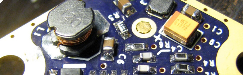
I wonder if he managed to pack both input and ouput filters on there – just by counting the obvious inductors there only seems to be an output filter.
I had one project messed up by conducted EMI, now I’ve become pretty paranoid about these things.
L2 and L3 are part of the input and output filters. L1 is part of the switch-mode converter.
I didn’t really understand from the comments in the link.
This looks like a PCB fitted into the bottom half of a TO3 case. But this is a PCB in the shape of a TO3? It looks like there are gaps between the blue part of the PCB and the gold tracing.
It’s a TO-3 shaped board. The solder mask is blue, and he has gold flashed copper extending all the way to the edge of the board with no mask on it.
Thwt’s what thought but if you look closely at one of the images, you’ll see what looks like a gap between the PCB and the trace giving the appearance it’s inset. It looks off center too. Shadow from the camera?
Yeah, I think its just shadow due to the mask layer being slightly raised. The picture of the bottom of the board shows no such edge.
Oh god…I want one!!!!! (or two)
Beautiful. I like the evenly spaced ground plane stitching at the edges. It would be a shame to put a lid on this, even if it makes it look “authentic”
“No, I don’t know why Commodore picked such enormous regulators for such a light load back then. They heat up because the input voltage is fairly high. I don’t know why either.”
If only HaD had someone at hand to answer that eh…
We could explain it, but then the kids wouldn’t learn anything. Damn lazy kids these days. They can look it up themselves.
If only comments in the linked thread explained this for us. I know that kind of convenience is a lot to ask, but one can dream, right?
Dimes to donuts, it was a matter of component cost savings in some form.
Bil Herd to save the daaaaay!
lm340 and 7805 are still around in a to-3 package for $2. I don’t see any talk of how RF noise was dealt with.
Poor man, you don’t see that this is a great hack. BTW, where do you find your $2 TO-3 ? Give a link please instead of trolling this entry. In mouser, such case cost 33$ (look at 926-LM340K-50/NOPB for example).
If RF noise is your concern, add an LC filter (but you have to calculate it).
For the sake of argument, Jameco has 7805K for $2.49:
http://www.jameco.com/1/1/2680-7805k-lm7805c-standard-regulator-5-volt-1-amp-3-pin-2-tab-3-analog-linear.html
They also have the LM323K for $4.75 if you want something more serious (3A).
I agree, however: great hack!
There’s plenty of cheap NOS on ebay.
To get rid of RF you’ll need a metal can around it.
Not too cost effective. Makes as much sense as making a surface mount replacement for a 6DJ8.
It seems to me there are lots of good reasons to build these kind of replica items even if it just to guard against being caught with no suitable replacement parts. You can also get better function. In this case, the device is sure to run cooler. I have a friend who makes replacement rectifier tubes (your comment reminded me of them). The contain a tiny micro and have adjustable turn on delay and also soft start that actually make is better than the original part it replaces (http://www.kitparts.com/51J-Collins/). Yeah, you could hack up the inside to have a board, but part of the joy of restoring this old gear is for it to look at least superficially authentic. What would you rather have? An Altair 8800 restored, a replica, or an emulator running in software? Cost isn’t really the issue when it comes to things like this.
I use the MuRata parts for 3-pin. About $3 for 5V or 3.3V
It looks gorgeous. I love how he went the extra mile and got ENIG.
OSHPark is always ENIG, so there’s that. The lack of mask on the back and the outline on top tie it together.
Someone in the thread pointed out that the gold flash pins and the ENIG finish might not be such a good idea with RoHS solder, and that leaded should be used for those.
There are some issues using gold with leaded solder (probably never bothered anyone other than the military), but we use ENIG finish with lead free solder all the time where I work.
I think the coolest part of this project is how he’s using it. He’s fixing up some retro hardware ( Commodore 1541 drive) and instead of just ripping out the old TO-3 package part and rigging some equivalent modern part in a different package in it’s place, he’s built a modern replacement that fits nicely into the existing part’s space and if he were to put a lid on it, it would look reasonable in place of the original part and not just replace it functionally.
I think we need a lot more projects like this if retro computing is going to survive as a hobby given that many components are a finite resource.
Should look towards the retro radio market for some tips. I don’t dabble much with it but from what I’ve seen, one common replacement is a two value cap. The radio guys take these apart, taking care to preserve the outer casing and pack the appropriate single value caps inside. Most of the time, the technology is there allowing the physically smaller caps to fit inside. Then a new paper bottom is made with new leads and wax (?) sealed and resoldered into place giving the appearance of original parts.
I guess the only drawback is you can’t see the new caps pop, thus neccessitating you repeat the entire process for replacement.
I can see the same being done for other parts I guess. Not sure how wise it is to have components misrepresent themselves with different “casings” when it comes to repairs or, in rare cases, valuation. I can see “mint” Commodore accessories being sold with replaced TO3 parts pushing those prices unreasonably higher.
A version of this has been available for some time with thermal shutdown and current limit protection at this site
http://www.ezsbc.com/index.php/products/psu5.html#.VbTpafnF1_k
Nice!
Hi everyone!
I never thought this would generate any interest. I am well aware that plenty of switching POL modules exist out there already. TO-220 drop-ins for example are pretty common. There are also integrated inductor regulators, etc.
I just wanted to see if I could dream up something like this for myself. I must not have looked very hard because I didn’t see the ezsbc project. :) Or maybe I didn’t want to know…
It wasn’t a question of not having linear parts, I have a drawer full of 78H05s and other TO-3 regulators, although I did notice that new TO-3 parts are deprecated or expensive on DigiKey et al.
I gave myself a few requirements:
1) Solidly-attached pins that won’t melt off when you solder the module in. Hence the press-fit pins. I also ordered some Harwin nail head pins and HMP solder. I think the Mill-Max pins work great. I have a friend who’s a reliability engineer, I’ll see what he thinks. I have also heard about the gold-gold problem. I don’t know what it is. It’s a pretty tight interference fit, surely the hex head cuts into the copper of the PCB? Anyhow, there is a tin plated version of the pin. But I’m sure they aren’t meant to be hammered in either!
2) Input and output filtering: buck converters are noisy-current-hungry on the input side. Bulk decoupling is provided by the end application, I just added small L-C filters on in and out to knock out any 1MHz + tones.
3) Easy hand-solderable packages with no thermal pads. I can handle smaller stuff/DFN at work, but at home I don’t have that much equipment. (I didn’t even bother putting a smaller tip on my iron, hence the somewhat blobby joints. Too much solder.)
4) Super slack routing rules with 10/10 rules as much as possible. So I can get the boards done anywhere. At 10/10 you can get one of those wise-cracking dinosaurs from The Flintstones to etch it for you. (“Eh, it’s a living”)
5) A measly 500mA output, with about 10V in.
The chip is the TPS54232. It provides all the thermal shutdown and current limiting. I added a fuse at the input side, for those oops moments. These days you don’t need to add or design these functions, they’re all in there already. It’s not like when I was in college and we used the LM723…
I spent most of the time reading the datasheet and app notes. I ran some LTSpice simulations on a generic buck converter. LC filters are trivially easy to calculate, you just need to pick a coil with high enough saturation current and low enough DCR. I mulled around different output caps and placements and came up with this design. Loop compensation was good enough with the default values in the datasheet. However further testing may reveal problems there.
Testing was very basic: 10R resistor on the output, regulated DC in. Run for 8 hours. Measure voltages: OK. Check temperature: barely above ambient I do have thermocouple thermometers but simulations suggested barely a 4C rise on the chip, and less on the diode and inductor. Not worth getting upset about. At 1 A out, it does get about 10C hotter. The TPS is only rated to 2A, not good enough for a general purpose 3A TO-3 replacement.
Further testing would be transient load, 50mA to 1A steps for example. 120Hz full wave rectified DC at the input. Capacitive load. Look at waveforms, not just integrated readings on a DMM.
The BOM cost is also pretty high, the TPS chip is not that cheap, and the super big output cap is a polymer job, also not cheap. It’s also probably not required.
I’m thinking of a re-spin with an AOZ part with integrated rectifier. I am also not very happy with the vias around the edge, the spacing is not equal. I’m amazed I sent out the artwork like that, but I got impatient. I also want to back off the copper some more from the pins on the bottom, and tweak the outline since it is a bit wider than most TO-3 packages.
The 3D printed cover idea would be more of a logo thing. If you have ever taken a 1541 apart, you’ll see that the Commodore logo pops off from the top case. I can copy that and clip it on the module. Ton3y is just for my rainy weekend fun. There is no rhyme or reason to it, especially if the existing ezsbc part is already out there.
Now that EzSBC has discontinued their TO-3 package switching regulator I’d love to see this become a product.