These are the times that we live in: the Raspberry Pi Zero comes out — a full freaking Linux computer on a chip for $5 — and people complain that it doesn’t have this or that. Top place on the list of desiderata is probably a tie between audio out and WiFi connectivity. USB is a solution for both of these, but with one USB port it’s going to be a scarce commodity, so any help is welcome.
Hackaday.io hacker [ajlitt] is looking for a way out of the WiFi bind. His solution? The Raspberry Pi series of chips has a special function on a bunch of the GPIO pins that make it easier to talk to SDIO devices. SDIO is an extension of the SPI-like protocol that’s used with SD memory cards. The idea with SDIO was that you could plug a GPS or something into your PDA’s SD card slot. We don’t have PDAs anymore, but the SDIO spec remains.
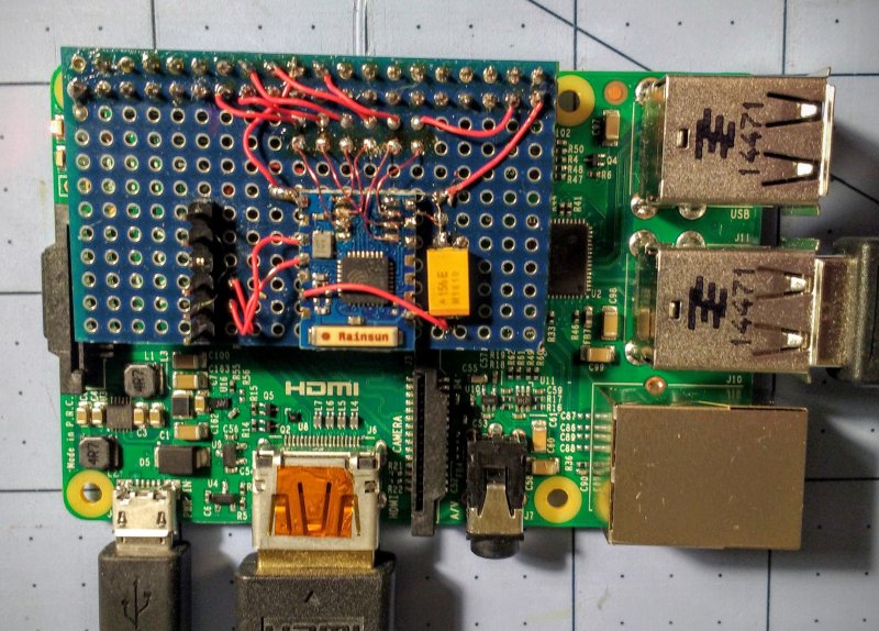
[ajlitt] dug up an SDIO driver for the ESP8089 chip, and found that you can liberate the ESP8266’s SPI bus by removing a flash memory chip that’s taking up the SPI lines. Connect the SPI lines on the ESP8266 to the SDIO lines on the Raspberry Pi, and the rest is taken care of by the drivers. “The rest”, by the way, includes bringing the ESP’s processor up, dumping new firmware into it over the SPI/SDIO lines to convince it to act as an SDIO WiFi adapter, and all the rest of the hardware communication stuff that drivers do.
The result is WiFi connectivity without USB, requiring only some reasonably fine-pitch soldering, and unlike this hack you don’t have to worry about USB bus contention. So now you can add a $2 WiFi board to you $5 computer and you’ve still got the USB free. It’s not as fast as a dedicated WiFi dongle, but it gets the job done. Take that, Hackaday’s own [Rud Merriam]!
Thanks [J0z0r] for the tip!


What is it with all these stupid hacks trying to make the Zero a full Pi?
Is it all just about the money?
Cheeper than an A+?
I’ll make you a hack that show of the size.
Idiots!
Oh, I’m sorry, I thought we were on Hackaday.com, where modifying devices was a celebrated pastime. May I direct you to Engadget, perhaps?
You must be new here. There is a vocal minority of comments on nearly every post that finds the subject unworthy of their specific hacker label. In fact in my years on the job, this is the defining characteristic of the of an engineer class or know-it-all technocrat, apply arbitrary and inconsistent criticisms in a dickish way.
Sorry, wrong thread.
But my stament is still true though.
So is this hack trying to make a zero more like an A+ by adding wifi to it…. just like the A+ which has built in wifi???
I cant even click reply on the post below making me Think its rom a HaD member.
But the hack will be based on the size and not WiFi.
(The A+ does not have built in WiFI. Neither does any of the Pi boards.)
@Michael Simonds
None of the pis have wifi built in. You have to use ethernet or a USB adapter.
Yes, [janostman]
you are new here.
HaD (Hackaday) only allows 4 levels of comments. Their reason is they don’t want indented follow on comments scrolling off the right margin of the page (like many other sites).
So, we just reply to the last comment that allows replies, and sometimes mention which reply we’re replying to.
Also we have a bunch of Grammar Nazis and trolls among the regular commenters. It’s all part of the HaD experience.
A hack is something you modify to reduce the cost of a project and/or do something with the stock device that can’t normally be done.
Since a $1 USB hub and a $1 wifi adaptor from China would easily and cheaply fix this issue, it isn’t much of a hack, but rather it’s more of a rube-Goldberg-esque waste of time and money.
I know some people disagree with this definition… and those people are wrong. Hacking was invented by a counter-culture that used their hacks to save money, do cool stuff and exploit the system. It’s a little cartoony but just rent Hackers or Real Genius, that’ll get you whipper-snappers up to speed. ;)
I won’t agree with the original poster as with the zeros very low price point there IS potential to do hacks to give it more functionality and still save time and money…. this just isn’t one of them.
Here is how you “fix” a zero…. I’ll just lay it out for everyone to save time:
1. Get a cheap usb hub the same general form factor as the zero.
2. Get a micro usb to regular usb cable as well as an adaptor for the hub.
3. Buy usb versions of all the missing stuff like wifi and while you are at it, maybe some cool add-ons like gps and Bluetooth.
4. Use risers to mount the hub above the zero, giving you the same general footprint and plug everything in.
Now the hub will be anywhere from a dollar to 10 depending upon what you want to get. The cables are around a dollar a piece and ditto for any usb dongles you pick up.
So for zero effort and an additional 5-15 dollars you can upgrade the zero and save the small form factor for the most part.
So any hack that adds functionality back will have to cost far less than a couple of dollars and take virtually zero effort to make sense. I thought the usb hub hack from the other day was worthwhile as you really need a hub for most applications, but the other ones thus far….not so much.
Point me to a $1 USB WiFi adapter (free shipping) that works well with the pi. Not trolling.
There are literally dozens of different brands of $1 USB WiFi adapters on AliExpress and eBay. For serious. They work fine on RPis. I have at least 4, because I keep losing them or taking them apart.
There are _no_ USB hubs for less than $7, so your points stands. And that one didn’t work properly, I had to spring for a $12 one, which starts to get into the “real money” territory when combined with a RPi B or whatever
Defines hacking as modifying hardware to do something other than intended. Craps on guy who mods a WiFi module, uploads custom firmware, all the while leaving traffic over usb free of WiFi.
You really haven’t a clue have you?
The above post says it all perfectly. Thank you [FlawInTheSystem]! :-)
I for one am happy somebody decided to make this work, it solves some issues for one of my own projects where the speed of the WIFI connection is less important than keeping the USB free for other purposes. Besides, this method looks like it takes up *much* less room than a full USB hub board, WIFI adapter and associated USB connector size converters and cables. I suspect its more power efficient too…
I agree! I really like this hack for its small form factor as well as the fact that I have a couple dozen esp8266’s that I am using for home automation. One of my main pet peeves with adding wifi switches and sensors everywhere is actually seeing wires or enclosures around the house. So I feel like this is a very useful hack and I will be using it! Thanks!
I think you’ve come to the wrong website :-)
Tror inte det. Sök på Hackady och Janost?
Tror inte det, sök på Hackaday och Janost?
It’s definitely not ‘cheeper’! Whatever that means…
Just load up a pi with a bunch of recorded bird wavs and wham, a cheaper cheeper!
You do realise that not only is the Pi Zero cheaper, it has twice the RAM of an A+? And A+ doesn’t have wifi nor ethernet either!
Idiot.
http://i.imgur.com/QSHAOoD.jpg
janostman: “Idiots!”
Says a man who tries to sell his synths here:
https://janostman.wordpress.com/
http://www.dspsynth.eu/
Quite a wrong attitude, this is a hacking blog. The project is really good and includes total hack.
Not all projects make “commercially” sense here. Like janostman’s synths (featured here at hackaday) which are not a hack, just a processor running “analog modelling” (whatever that means) sound generator.
7 years later and janostman has quit selling on those url. Sais alott, meanwhile I think this SDIO wifi hack is awesome and can be used elsewhere too. its the little “useless hacks” that can actually make a difference somewhere else.
BuT UsB HuBs AnD CHeAp DonGlEs.
Your not worthy of HaD, go back to the electronics facebook group (its so full of “n00bs”, trowing dongles and “schematics” arround without reading datasheets.
Meanwhile this hack actually also documented ESP different boot methods and undocumented functions. Its a awesome hack, but not for everyone
It would be new to me, that the “full Pi” had a Wifi on board. But perhaps only mine has not, because it is of the first generation???
It would say, this all is just for fun, for hacking and learning.
tell me, how does it feel to get torn a new one?
“buy this… buy that… buy these…”… which is the excitement of doing that??
this site is called “HACKADAY”, not “BUYADAY”…. for a reason
amazing!
AFAIK ESP8266 and ESP8089 are same silicon with different boot ROMs.
I proposed adding the ESP8089 on the RaspPi Zero thread:
https://www.raspberrypi.org/blog/raspberry-pi-zero/
Gordon Hollingworth says: it will cost £300,000 in engineering
I begged to differ with him on that number.
100k€ for EMC testing?! That might be reasonable for verifying the full protocol interoperability of a cellular modem or something, but for emissions testing an integration of a known-good wifi chip… Omg.
That was £100,000 – British Pounds ==== 138,000€ – Euros
EMC testing isn’t cheap…
Probably $10,000 in US/EU shop. Under $2,000 in Chinese FCC certified lab.
$151,000 (£100K) estimate is a bit excessive.
They haven’t integrated RF stuff before, so they might roll in some safety margins in case the layout doesn’t work the first couple of times. They might have to do a board respin, a small proto run etc. as they need a production ready board for these test. All of those would cost money in additional to engineering time, booking lab and rerun tests.
If you are not using an already certified wifi module, $100k is the number I’ve heard thrown about to get a device tested, certified and registered with the FCC as an intentional radiator (unintentional radiator is much more simple, and thus MUCH cheaper). This is why certified modules exist.
What are the rules for a non finished good ISM band module like this? Sparkfun sells a couple of custom ESP8266 boards and I don’t think they’re licensed. Would the RPi Foundation need certifications to sell in other countries?
Certification isn’t too bad if you include an antenna on the PCB.
There is also a legal way to avoid – ship the product without firmware. Then it doesn’t have to pass FCC since it is not a functioning product. The end user then loads the firmware which makes them responsible for certification. I suspect you can’t ship too many boards using this loophole.
The modules from Adafruit using the ESP12 are legal. The Sparkfun ones might be legal, but there is nothing I can see supporting that. I’d lean toward them not being legal.
If you shop around at Chinese labs you can get FCC ID for modules like this for under $1,000. It is legit ID, you can look up the labs in China licensed to do this on the FCC website. After they grant the ID you will be able to look up your board in the FCC database. You can’t fake this, the FCC is the one that enters the stuff into their database.
AFAIK you’d have to work at it to make an ESP module that fails FCC, so most of these board would pass if submitted.
Nice work!
I have an old ESP-01 with 512KB flash that I may try this with. Besides lifting the SOIC-8 flash chip, I’ll lift the esp8266, cut the trace from GPIO15 to the ground pad, and re-solder it.
If I screw it up, at least I’ll get some solder rework practice, and I’ll have a 512KB flash to use for other projects.
Such a great hack. It show a little bit behind the scenes of the chinese connections. Thank you very much, a masterpiece!
The thing is that you can stick ANYTHING onto the GPIOs on PI and make it work.
Just need the right driver? :)
Not anything – these Pi’s really hate 5V… I mean it… they can’t STAND 5V!
Yes they can if you do it the right way?
Are you providing an answer or are you asking a question?
Sorry? You use the GPIO ouput straight into 5v logic and you put the 5v logic into the Pi with a slight handicap (or some resistance :) ) to lower te level. Not a big issue. Never has been.
@janostman: The Pi still cant stand 5V. If you add a resistor it does not get it and is happy. In teh other direction: Therte are 5V peripherals which will NOT wrk with 3V3 input voltages, or at least not reliably. WS2812 strips are one example. Not reliable without a level shifter (74HCTxx).
Set apart the early arduinos, everybody hates 5V
Well, I’m a crusty old timer, grew up with 5V TTL
+1. And I’m a crusty new timer that grew up with 5V PICs from Microchip. Good stuff, 5V.
well, my ESP-01 survived a few minutes( due to my puzzlement) connected to a Sparkfun 3V3 FTDI usb to serial cable that surprisingly outputs 5V. I bought the cable several years ago and forgot it had been sold mislabeled
that ESP-01 is currently running some test code on it.
It’s a little unclear what he actually achieved in terms of performance, in particular whether he got 4 bit SDIO mode working. If he did then that,. at 50Mhz clock ought to give fairly reasonable throughput, possibly constrained by the ESP chip.
I don’t understand all the negative comments here – this is not just lashing an ESP8266 via a slow serial link. It’s a double hack – figuring out that the Pi supports a hardware SDIO port, and that the ESP can run in SDIO mode. Result (assuming it actually works – again this wasn’t made too clear….) – a very cheap Wifi interface that doesn’t use a USB port. Many potential apps don’t care about speed, so getting _some_ useful wireless connectivity at minimal cost and IO is a useful achievement,
The stuff about huge development and approvals cost is of course complete bollocks.
Unfortunately I haven’t figured out how to get the kernel to tell me what it thinks the SDIO bus mode is and any bit error rates.. But I can see transitions on all four data lines when pushing WiFi traffic and I can see that the clock is 50MHz. If it were degraded to 1 bit SDIO or SPI then the upper two data lines should stay idle.
What sort of throughput do you get?
~1.5Mbits tested with iperf to a router sitting a foot away. The WiFi link is reported as 54Mbps at both ends, so I don’t know where the bottleneck is.
(fast) transitions on all lines would be a good indication of 4-bit mode, Another simple test would be to disconnect D3 while running and see if it crashes..!
And maybe also compare speeds (sending & receiving large packets to maximise influence of raw bandwidth) with 1 & suspected 4 bit mode, assuming it can work in both.
Should take a look at the WiFi RF signal levels just in case.
Literally the only comment worth a damn so far.
Seeing Mike defend my project from trolls made my day
Brilliant!
I’m now officially waiting for someone to write a modified firmware and driver for the ESP8266 that emulates a USB host port through it’s GPIO pins. (Or hacks in a Arduino USB host shield onto the SPI bus)
Why don’t you write it?
I lack an ESP8266 and the equipment to do soldering on this level.
ESP8266 is $2. You are telling me that you can’t spend $12 to buy half a dozen of ESP8266 to practice on…
Hot air rework tool is around $60 and not that expensive either.
Since I wrote that, I’ve seriously gotten into this. I’ve already ordered 4 from Ali Express ($10USD) (The ESP8266 has been on my list of things to play with for a while now)
As for the actual physical work, looking at it again, I think my soldering skills and equipment are up to the task. I don’t believe that I’ll need a hot air rework station. I think I can get away with a finer tip on my existing soldering iron if it comes down to that.
it’s been… 2 hours and 55 minutes. are you sure you’re actually into it?
ali will take at bare min 3 weeks to deliver.
@wumbologist We’ll see =)
USB host stack isn’t as simple as you think. Those Arduino examples are low hanging fruit and don’t even cover all the transfer modes and minimum set of features. You’ll need to write OS level drivers for each and every single piece of hardware you wish to interface to.
You should also realize that the RPi has USB hardware and linux has full working driver stack already – just missing a cable and/or a hub. The Maxim chip (or most of the OTG on ARM or USB host chips) aren’t implementing the more popular hardware programming model OHCI/UHCI/EHCI.
http://www.beyondlogic.org/usbnutshell/usb1.shtml “USB in a NutShell” also be prepare to run the official USB specs.
[tekkieneet] you’re assuming I haven’t thought of that already.
My rapid reading of the Maxim details are that it’s a USB transceiver that communicates over SPI, and support for different devices needs to be implemented in whatever it is that’s on the other end of the SPI bus. My understanding of the Arduino library is that it’s essentially the same thing, only implemented in an ATMEGA instead of in a dedicated chip and using an API instead of SPI.
Linux supports a lot more USB host chips than just OHCI/EHCI/UHCI compatible ones. Writing a driver for, say, the Maxim chip shouldn’t be that complicated. (It almost wouldn’t surprise me if there was already one out there somewhere.)
I shouldn’t need the USB specifications. I’ve got a documented USB PHY on one end that talks to me at a higher level than the actual line protocol and a high level API at the other. Writing code that translates one to the other shouldn’t require a trip to the USB specifications.
http://comments.gmane.org/gmane.linux.usb.general/102451
>The Maxim MAX3421E is the other option, but it has no Linux driver.
The chip basically implements OHCI over SPI
rather than PCI. Anybody know of any particular reason why there is
no Linux driver? Has anyone already written or
attempted to write an OHCI-over-SPI driver for MAX3421E?
:
>ISTR that the MAX3421E does not in fact have an OHCI register interface;
I believe it’s some proprietary thing. If I’m right, that might help
explain why there’s no Linux driver for it.
[tekkieneet] Thanks for that, I’ve added it to my notes.
>>ISTR that the MAX3421E does not in fact have an OHCI register interface;
>I believe it’s some proprietary thing. If I’m right, that might help
>explain why there’s no Linux driver for it.
huh? Even included in mainline
http://lxr.free-electrons.com/source/drivers/usb/host/max3421-hcd.c
[Claude] Dammit, why didn’t I punch that into Google myself?
Thanks!
ESP8266 is the wrong part to do host USB. USB host is a pain and you are making worse to do bit banging.
Would be easier to find ARM chips with OTG and with USB stack.
This isn’t about being “easy”. If I wanted easy, I’d hook up a hub to the existing USB port.
This is about dealing with part two of the “problem”s with the RasPi Zero: Only one USB port. We want to hook up (at least) a keyboard and mouse, so therefore we need (at least) a USB 1.x port.
Over the past two hours I’ve done a bit of research, and there’s a few ways to do this. There’s a soft-USB-host library for Arduino which implements all the USB protocol stuff using two tristate buffers and some hand crafted assembly. Alternatively, there’s a USB-host shield for Arduinos which uses an SPI=>USB chip from Maxim.
As I see it, there’s now three routes:
1. Implement the soft-USB-host library on the ESP8266 without disturbing the WiFi code.
2. Use the soft-USB-host library on a ATMEGA328 and connect this to either chip.
3. Connect the Maxim chip to the RasPi over SPI.
Given the time frames I have (I have now ordered an ESP-03) I’m likely to go with option 2 (I have ATMEGA328s lying around) and try to figure out a way to use the ATMEGA as a USB host peripheral. (Maybe make it emulate the Maxim chip? I don’t know.)
Shove a Bluetooth adapter into the USB and you can link up a mouse, keyboard and more to one port.
Hubs are cheap and they work. Some monitors/keyboards have built in hubs.
Still not entirely sure what you are trying to do. Seems like you idea isn’t well thought out.
– ESP8266 does not have an extra SPI as its SDIO is tied up with the RPi0 So ESP8266 shouldn’t be part of the equation. Similarly, Atmega does not have 2 SPI and the one SPI is slow.
– If you are going down the path of the Maxim chip, hook it up to whatever pass for SPI on the RPi directly.
– The RPi0 already has a USB OTG PHY that the os supports. You just need a hub and a cable. Maxim chip needs a hub too.
– PS/2 mouse and keyboard from surplus store with a bit of level shifting and small coding can be interfaced to the GPIO.
Far more interesting is the new ESP chip with Bluetooth + WiFi. Now if it would work similarly as this proof of concept hack. Spite left a comment to OP, so hopeful there would be some help getting this hack into a working state.
This stopped being about easy yesterday, this is now about whether or not I can add a second USB host controller and how much trickery is required to do so.
The plan is one of the following:
1. RasPi => SPI => Maxim chip => USB
2. RasPi => SPI => Arduino + Soft USB Host => GPIOs => USB
3. RasPi => SDIO => ESP8266 + Soft USB Host => GPIOs => USB
I’m planning to go with option #2, and I’m planning to have it emulate the Maxim chip.
I haven’t checked whether I can sneak a SPI bus out of the GPIO connector on the RasPi with the SDIO pins being used, however I’m confident that there’s a way to do that. If there isn’t, just adding a second USB host controller would meet my goals.
To be honest, I’m not interested in Bluetooth yet. That said, most Bluetooth chipsets communicate over serial, so adding one shouldn’t be a problem.
>1. Implement the soft-USB-host library on the ESP8266 without disturbing the WiFi code.
Not likely to work in ESP8266 as the USB stack will have a lot of interrupts for the packets, scheduling etc that will interfere with WiFi. You’ll need to off load that work to a separate processor. Maxim chip is actually more expensive than ARM chips these days. I have looked at the issues before and I took the ARM chip path.
A rapid reading of the details on the arduino soft-USB-host library I found makes it look like it’s designed around doing all it’s USB stuff in function calls and leaving the bus alone otherwise. (IIRC all USB transfers are host initiated so this makes sense) Therefore, assuming it doesn’t take too long to do USB stuff, the hybrid driver / firmware could just switch between USB and WiFi as needed. (WiFi has power saving modes which essentially involve switching off the transceiver for a “moment”) Of course this leads to the eventual problems of ensuring some level of quality of service for USB and WiFi, but this is a hack, so it probably doesn’t matter. (My main “not disturbing the WiFi” issue is one of space. Soft USB implementations tend to require a lot of code IIRC)
I completely agree that adding an ARM co-processor or using a different ARM dev board is the best option. I could easily obtain a dev board that has multiple USB ports and a WiFi chipset built in, but this is, again, a hack, so “easy” and “better” aren’t necessarily wins.
I see this like adding a Raspberry-pi to a ES8266, just to make sure that your suck even more power.
Or adding an ESP8266 to a Raspberry-pi, to get a wifi unable to stream anything with a useful bandwidth.
Those devices are not meant to be friends.
Anyway, do it, just because you can.
You do realise that your Android phone and / or tablet more than likely uses an SDIO WiFi/Bluetooth chip, right? I’ve _never_ seen bandwidth issues on any of my Android devices, most of which are cheap Chinese shit.
Define “Useful bandwidth”. Many applications just need “Some bandwidth” or even “Any bandwidth at all” for minimum cost and/or port usage and/or size.
If you need high bandwidth there are already solutions for that.
He’s getting 1.5Mbit/s throughput. Literally faster than my parent’s broadband Internet! Okay it’s only a foot away, but still substantially faster than the 56k dialup I had for years.
Your comment reminds me of the folks who swore that the 480Mbit USB 2.0 bus on the Raspberry Pi couldn’t possibly provide enough throughput for full 100Mbit Ethernet, therefore “herp derp the Pi’s Ethernet sucks!”, never mind that 480 > 100 by a factor of 4.8.
Simple math, but idiots abound, as you are also proving by your comment.
USB has higher bandwidth, but your factor 4.8 is wrong. Ethernet is full duplex while USB is half duplex and have to carry side band control packets and overhead, so it is closer to a factor of 2.
seems hackaday.io is so braindead NO ONE read linked project ?
“~300kbits” is the keyword
The author of the project is in the comments a little further up with ~1.5Mbits. It’s not enough to stream video, but plenty for a number of applications.
Should be able to stream some internet radio. It’s a very small form factor,
oh wow, I thought it was because of bad interface, but its YOU.
Author said it himself – 1.5mbit _when sitting on top of a router_
its a great hack, but useless for regular use
hey, it’s ~1000x as fast as Voyager 1’s downlink. not bad if you ask me.
awesome ..
Could the low speed have anything to do with the pi and pref board bring so close to the antenna?
I would try hanging the pref board off in the other direction with the esp board/antenna sticking out.
My NodeMCU signal sucked until I started hanging it off the breadboard.
I stupidly made this mistake. And the perfboard I’m using is salvaged from some old devkits and have a copper flood in the inner 2 layers, which is even worse than the usual single sided copper donuts on phenolic.
A couple of days ago I carefully nibbled away the area directly under the antenna, and I think it may have helped a bit.
Or bad/weak power supply as this hack doesn’t not have it own power, ceramic antenna got damaged in the hack, RF circuit DOA, localized WiFi interference etc.
scope the power rail on sag during transmit, look at the signal strength on both sides of the connection etc
wow, so much negativity!
This is mavelous! a great hack – and it’s a hack! it something made to work in a way it wasn’t intended.. I absolutely need to give this a go!
I think this is a awesome mod. Keep up the great work. There are a lot of people here that don’t know much about Raspberry Pi or how to add wifi to it. This will help them. Again thank you.
Cool. Nice work! Any updates since last year?
Lots! Check the hackaday.io project.
I found that the “USBMan” adapters work well if you add a pigtail to them.
Well thx for “the necro” atesin…
I have a half pondered “Make something actually useful out of an old WinCE GPS” potential project, and got as far as thinking SDIO, I should look into that, I might be able to abuse the lines for wifi… and here we go… if I can sort out the software end on WinCE or a linux that will boot on the Samsung SOC
sometimes i found replies like…. (trying to attach a battery to my home server) “you are a fool cracking your head.. just BUY AN UPS” …. of course i know i can buy an ups!!!, but maybe i have no money, or maybe i found very fun and educative to try build one myself … comments like those get me a little angry, i didnt notice the date, sorry
i accidentally found this article … i have an usb printer, a raspberry pi 2b, and an esp-01s (esp8266 8pins 1mb) … a would like to build a raspberry+esp wireless print server (cups?)….
maybe by plugin the esp -01s to the raspberry as a “wireless network card” (wlan nic), and a special linux kernel module (device driver emulator) that make the system think it has a real wlan device
i dont know if somebody has done something like this