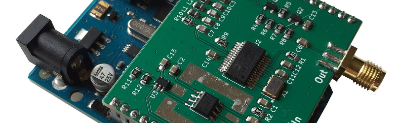
What do you get when you combine a direct digital synthesis (DDS) chip, a power detector, and an Arduino? [Brett Killion] did make that combination and wound up with a practical network analyzer.
The project uses an Analog Devices AD9851 DDS chip clocked at 180 MHz which will output a sine wave at any frequency from 0 Hz and 72 MHz. A Butterworth low pass filter processes the DDS signal and then feeds a two-transistor amplifier. The circuit will output about 0dBm into 50 ohms. The power detector is an Analog Devices AD8307 along with a 50-ohm input load. There is no filtering on the power detector so it can measure from very low frequencies to 500MHz.
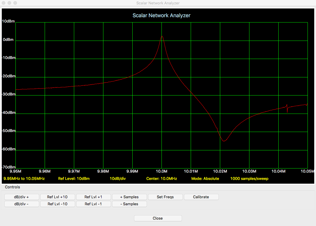
[Brett] uses a Python program to process the data from the Arduino. For example, here’s a plot of a 10 MHz crystal from the software:
If you want to know more about DDS, our own [Bil Herd] has you covered (see the video, below). We’ve also seen similar antenna analyzers that are about the same thing.


i have been thinking of making somthing similar with an HMC833LP6 PLL for some time now
This is a wonderful piece of engineering. Perfect for analyzing low pass, high pass, band pass filters or any other resonant device or circuit up to 72MHz. Well done.
Thanks!
For people who would like to build something similar, but a bit simpler (and mainly for testing audio equipment because of limited bandwidth) Analog Devices has AD5934, which measures both real and imaginary impedance and phase shift for single frequency of for range of them. I haven’t time to play with it yet, but I might try it with either CHIPKit or PIC32MX250 Pinguino in near future…
If it could go up to 108MHz it could be used to test resonance of FM broadcast antennas. Nice piece of work.
Thanks! I would love for it to go higher, but this seemed like a nice first piece of DIY test kit and the AD9851 is so easy to use and get (although kind of pricey at $25) that it was a pretty easy design decision. Especially since it covers the shortwave bands (up to 30MHz I think) making it useful for home brew Hams.
You might consider adding a module with PLL and VCO, and drive the clock input of PLL from your DDS output. One design could be used for different bandwidths by changing the values of some VCO components. This also won’t require any changes to the shield you designed.
This could also clean up the phase noise a bunch.
That’s a good idea, it could be separately powered (or jumpered from the Arduino 5V) and just plug right into the output SMA, spin it up to much higher frequencies, then spit it out it’s own SMA. I think getting up to 500MHz wouldn’t be too difficult.
damn! I was actually looking for a like button :-)
Thanks!
Awesome project Brett. I love the idea of making your own instruments. Gives a ton of learning.
Thanks! I know I learned many things (mostly by screwing them all up on Rev 1…).
We have this already and even better: NWT-7 or NWT-502.
There is the Poor Ham’s Scalar Network Analyzer project. It is an active group that’s making excellent progress. Unfortunately the project is on Yahoo Groups. Do a search for the PHSNA group on Yahoo Groups.
Awesome — I will have to check that out! I have been following another group, Scotty’s Spectrum Analyzer, and I want to basically use his system architecture with some modifications (not use a cavity filter and not use LPT for control, for example) and put it into a single board.
You can also check out this spectrum analyzer project that uses a TV tuner: http://www.elektroda.pl/rtvforum/viewtopic.php?p=9261913
Those DDS chips don’t have many fans among HAMs because of phase noise or other quirks related to their digital nature; did you encounter any problems in that context?
I didn’t measure phase noise or anything (I’m not even sure if that matters on a scalar network analyzer) so I can’t speak to it, however, I would have to think it would be at least comparable if not better than an LC oscillator for radio work. It looks like a pretty clean sine wave coming out of the filter (also it looks clean before the filter but as I only have a 70MHz scope, there could be many higher frequency issues I simply can’t see).
The AD985x series of DDS are probably the most popular and frequently used chips in HAM home brew projects. Most of the comments about phase noise has been about PLL chips like the SI5351. The general consensus is either type will be adequate for the HF frequencies under 30 MHz. For a wideband system like a SNA, phase noise might add a few dB to the noise floor, but will have a negligible effect on the readings you get. I built a small self contained SNA with a built in display several years ago, and have found it to be invaluable when working on many of my projects.
There is an interesting VNA project that I am thinking about called the VNArduino. It uses much of the same hardware as this project, but uses a AD8302 instead of an AD8307 to get phase as well as amplitude information.