After years of cutting my hands on the exposed threads of my Prusa Mendel i2, it was time for a long overdue upgrade. I didn’t want to just buy a new printer because it’s no fun. So, I decided to buy a new frame for my printer. I settled on the P3Steel, a laser cut steel version of the Prusa i3. It doesn’t suffer from the potential squaring problems of the vanilla i3 and the steel makes it less wobbly than the acrylic or wood framed printers of similar designs.
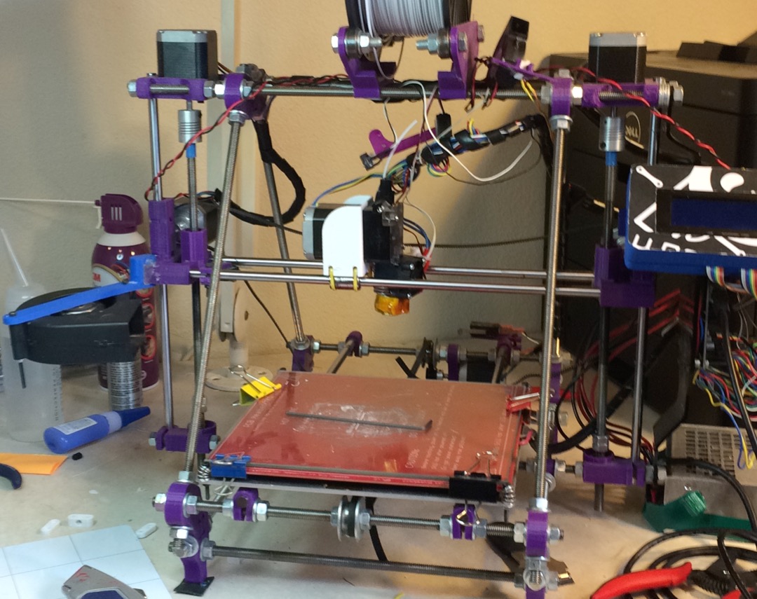
I expected a huge increase in reliability and print quality from my new frame. I wanted less time fiddling with it and more time printing. My biggest hope was that switching to the M5 threaded screw instead of the M8 the i2 used would boost my z-layer accuracy. I got my old printer working just long enough to print out the parts for my new one, and gleefully assembled my new printer.
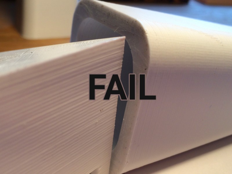
I didn’t wait until all the electronics were nicely mounted. No. It was time. I fired it up. I was expecting the squarest, quietest, and most accurate print with breathtakingly aligned z-layers. I did not get any of that. There was a definite and visible ripple all along my print. My first inclination was that I was over-extruding. Certainly my shiny new mechanics could not be at fault. Plus, I built this printer, and I am a good printer builder who knows what he’s doing. Over-extruding looks very much like a problem with the Z-axis. So, I tuned my extrusion until it was perfect.


It didn’t work. My next target was the threaded rods. I suspected them because the supplier I had purchased the kit from sent me really awful smooth rods. They were un-hardened, un-ground, un-straight, regular old steel rod stock. Useless as ways for bearings. I ended up having to cut the rods from my old printer up, cancelling a project I had in mind for them. So, logically, it followed that the threaded rod they sent me was garbage too.
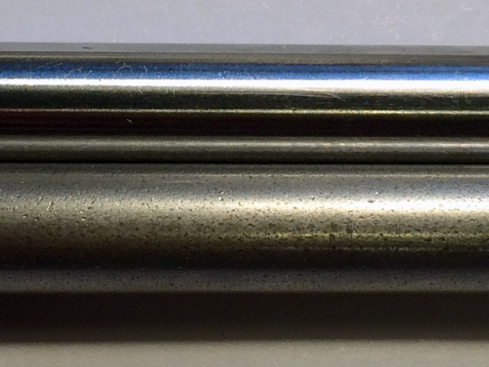
I ran to the hardware store, purchased a brand new M5 rod, some new M5 nuts (with a real class rating on them this time), and went home. I spent an hour straightening the rods until they rolled on the surface of my desk with no obvious high spots. I installed the new rods in place of the ones that came with the printer. No result. In fact, the new rods were wobblier than the old ones.
I was getting a little frustrated at this point. I fired up a print and watched my printer as carefully as I could, noting any visible deviation. I was using a bit of rubber tubing as the coupler for my z-threaded rods and the stepper motor. While I was watching the printer run, I noticed that occasionally the threaded rods would slip in the coupler for a half turn and then return to their previous orientation the next time the motors reversed direction. Aha! I took apart another project, and robbed them of some spiral cut flexible couplings. I replaced the rubber tubing.
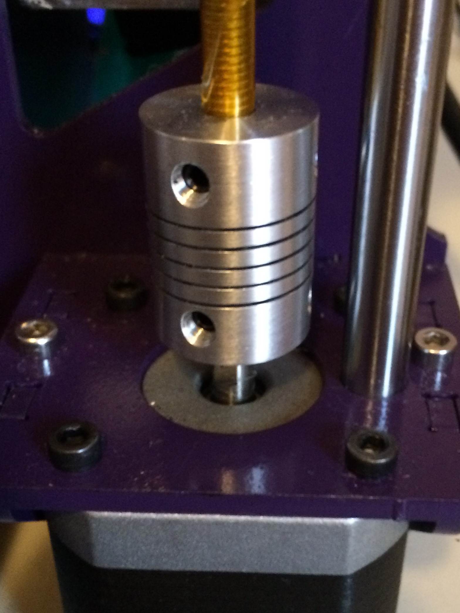
I was flabbergasted. The print quality barely improved. How? I had fixed an obvious visible flaw in the printer. Apparently the slipping was repeatable enough that it just worked itself out of the equation. Okay. Well, I noticed that since the inner diameter of my couplers were not exactly matched to the threaded rod, the rod was not perfectly aligned with the shaft of the stepper. That could cause some wobble. So I spent some time with kapton tape and got the threaded rods running as centered as I could without running out to use the lathe at the hackerspace.
Surely that’s it. I’ve replaced nearly every component on the Z at least once. Alas, still wobble. I was about to give up any claim to technician, engineer, hacker, etc and go study yodeling or consider vagrancy. I decided to look closely at the printer one more time and see if I could spy anything, anything at all, wrong with the Z.
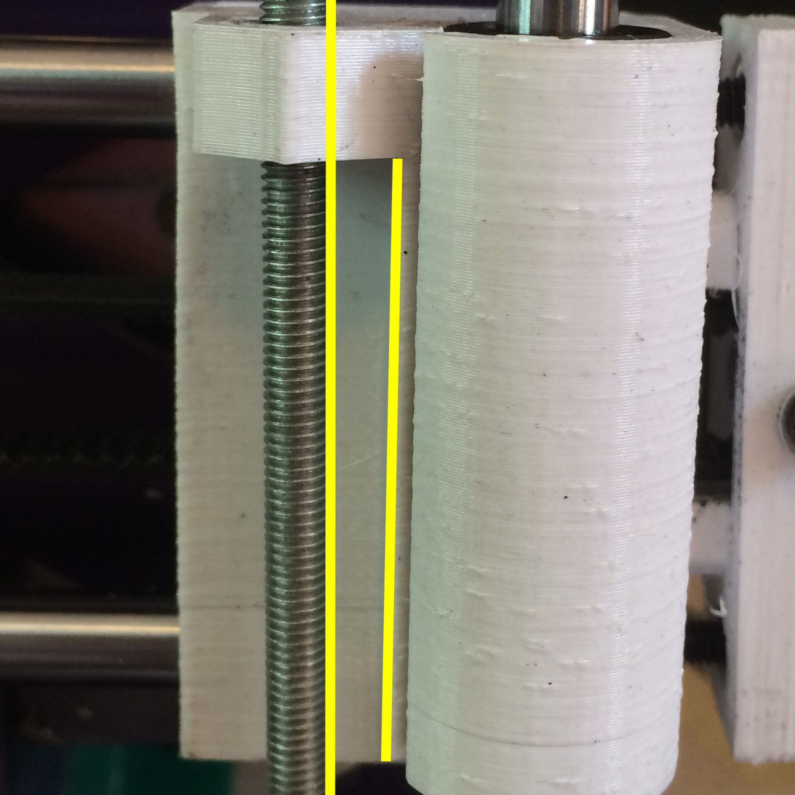
That’s when I noticed, when looked at closely, the Z rod appeared to go into the lead nut at an angle of a degree. If the lead nut was going in at an angle that meant it had to bend each time it turned. Which would be 100% the cause of wobble, but there was the problem with the theory. How does a rigidly held rod and a precisely placed threaded rod even get out of alignment?
My first thought was to blame my old printer as this part was printed on it. The i2 had problems printing square. Things were often parallelograms, especially in the Z (entirely my fault). So perhaps the part that held the nut and the bearings weren’t square. If it was leaning one way or another it could certainly cause this problem. So I carefully printed out new parts and reassembled my printer exactly the way it was before. I know my new printer is square. I measured. So these new parts have to fix the problem. They have to.
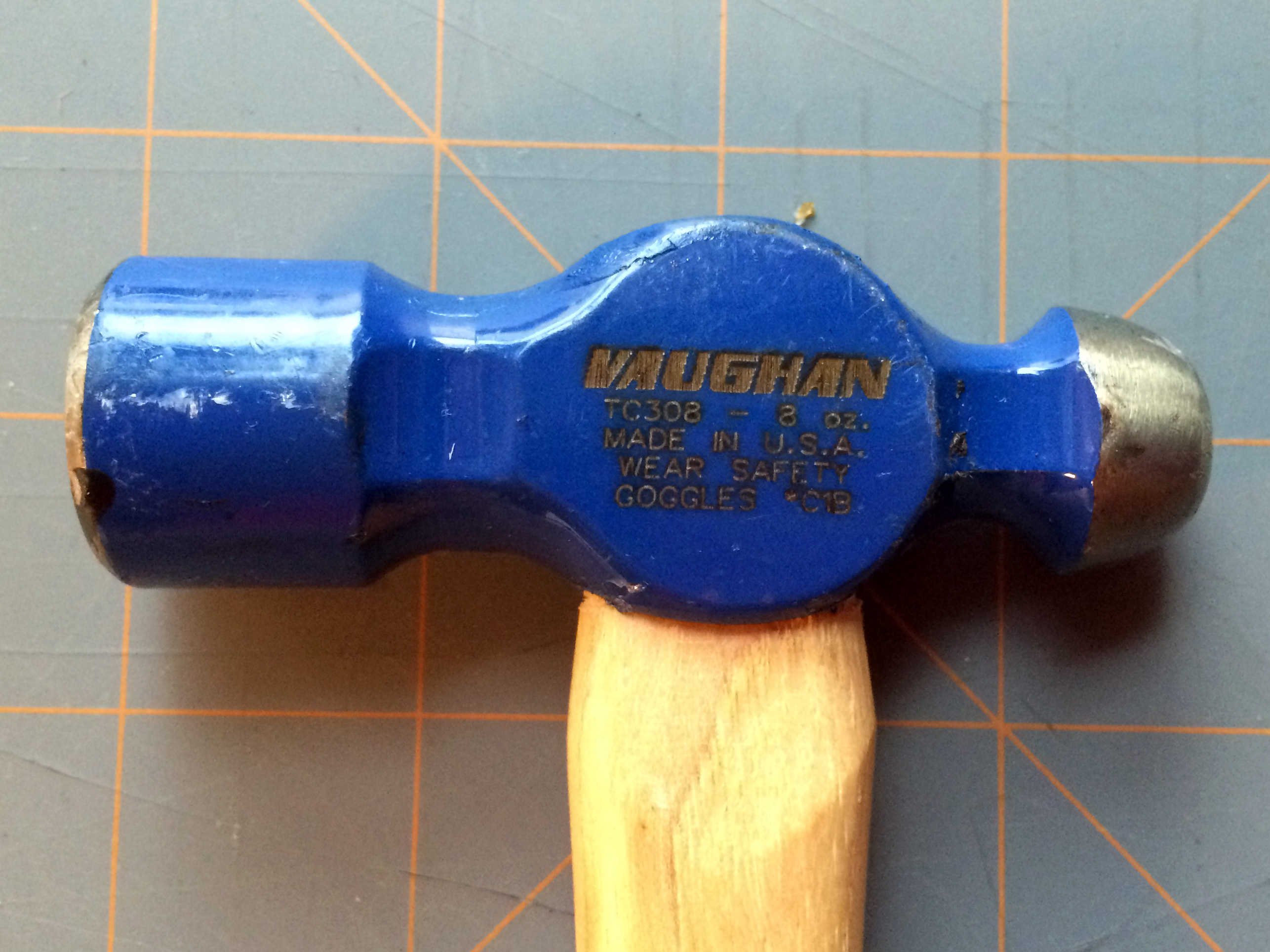
Vagrancy, right? I mean, the fresh air, not having to do laundry, occasional free food, and just walking the land. Living day by day… Despite the new parts, it was still wobbling. What else could I possibly fix? So I sat and really thought about it for the fiftieth time or so, and to my surprise, I figured it out. It was time to get out my precision mechanism adjuster.
My logic went like this. One side of the mechanism holds the smooth rods for the X in place. The other side has holes that go all the way through the part. When you assemble the printer you’re supposed to slide the rods through the one part and seat them in the other. Well, me being clever, I reamed out the holes of both parts to a snug press fit. (For plastic you can chuck the smooth rod into a drill and run it through the hole, and it will actually cut a pretty good press-fit.)
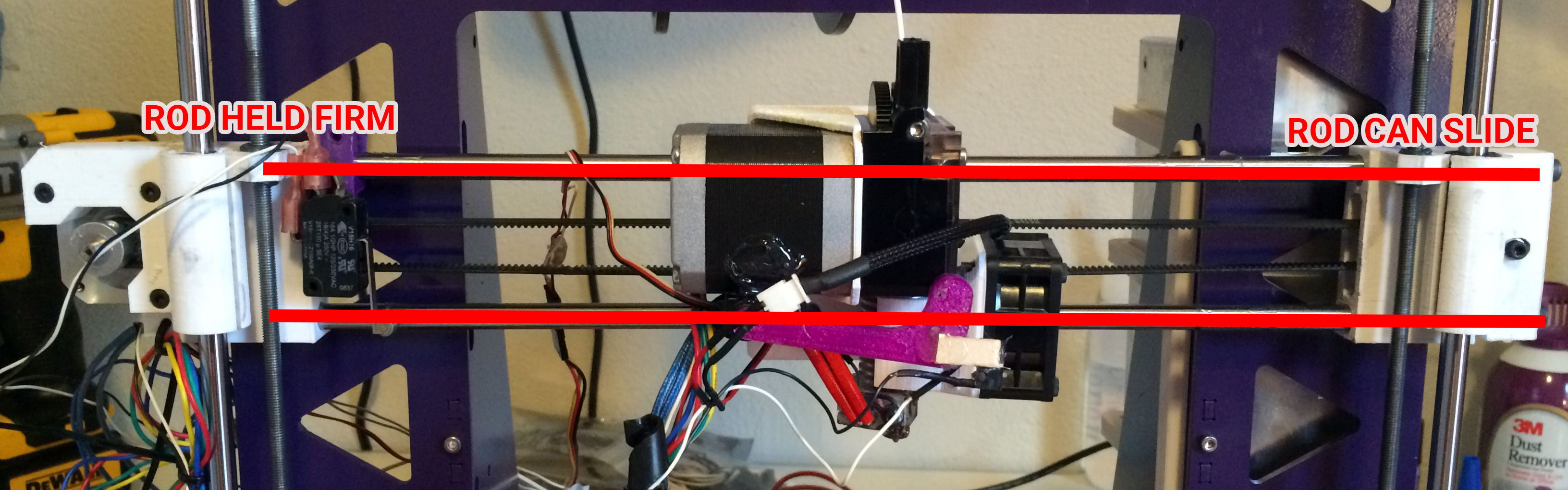
This resulted in both sides being able to hold the rod very securely. The design of the toolson P3 is very clever. One side holds the rods stable. The other side can slide. It may seem like if the rods can slide the machine would be imprecise, but it’s not so. The rods hold the nozzle in its Z position only. The direction they can slide is the X. However, the nozzle’s X position is determined by the belt. The rods are not involved at all. The belt is tensioned through the rods to the part that holds the stepper. So, the X position of the right carriage doesn’t affect the X position of the nozzle at all.
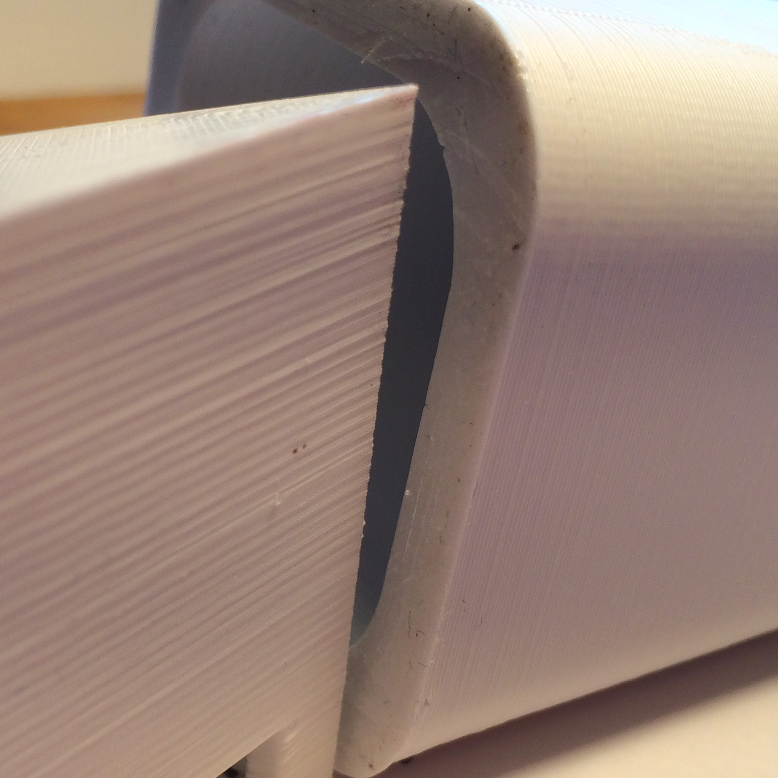
That was a lot, but in theory it means that if one side can slide it should self align to the Z-rods. It should be theoretically impossible to get the Z-rods out of alignment if the rods are held in place properly. That is, unless you intentionally make the through holes a press fit — which is where I failed. So rather than the part sliding along the shaft until it rested comfortably at its equilibrium. I could pick a location on the shaft for it to sit. I was being OCD so I made sure my shafts lined up perfectly with the end of the plastic part, bending both rods inward. This caused the angle I was seeing.
I tapped it with my precision mechanism adjuster, which gave it enough force to get over the static friction and spring close to equilibrium. I fired up the printer. Lo and behold, my Z was dramatically improved. The title picture has a before and after.
I still have some issues (probably because I broke a lot of things trying to fix this). My Z isn’t perfect. My next steps are to order lengths of threaded rod from McMaster because their rods have a tolerance on the thread and will hopefully be straighter. I also want to replace the stainless steel nut with a brass one for a better fit.
I also would like to reprint the through-hole part and ream it to a nice sliding fit. Theoretically this will solve my Z issues, but hey, it may be just something else. Anyone else have a similar debugging story?
 Fail of the Week is a Hackaday column which celebrates failure as a learning tool. Help keep the fun rolling by writing about your own failures and sending us a link to the story — or sending in links to fail write ups you find in your Internet travels.


Nice, I like the way you put the photos (with annotations) at the spot in the story that called for them.
Thanks!
why stick with threaded rod, get some acme screws if you want decent accuracy.
This issue ended up having nothing to do with the threaded rod, so ACME screws would not have helped. It is a planned upgrade:)
I think he’s replying to the plans you laid out at the end of the story, where you wrote: “My next steps are to order lengths of threaded rod from McMaster because their rods have a tolerance on the thread and will hopefully be straighter. I also want to replace the stainless steel nut with a brass one for a better fit.”
I’m unfamiliar with ACME screws, personally, are we talking about replacing the threaded rod with a long machine screw of some kind?
Ah. ACME describes a trapezoidal thread profile that’s better for transferring linear motion. Mainly because it’s a much thicker thread profile than a triangular one like the one found on an M5 thread. However, it’s not guaranteed to be a better thread overall.
For example, the reason cheap threaded rod works in 3d printers is that the lead nut (a regular nut) is always preloaded by the weight of the extruder assembly. The fine thread and thin cross section of the M5, if used with an appropriately matched nut, is capable of providing the needed resolution.
An ACME screw he’s referring to helps not because the ACME thread is necessarily better or more precise by nature. It helps because it’s a lead screw. Which means that, ideally, it must be made to a tolerance which makes it useful for linear motion. The tolerances it provides that a M5 screw doesn’t is: One, a better fit between the lead nut and the lead screw. Two, a straightness tolerance. Regular threaded rod is mainly used in static tension, which means it will straighten out under load. A lead screw bears dynamic loads and defines position. It must be straight.
The reason I am going with threaded rod, for now, is price and time. It’s very cheap and can give good results with care. I also don’t have the time to machine/design the necessary parts to properly adapt a leadscrew to this frame in a way that makes me happy.
price shouldn’t be a problem no more, they are selling a pair with the nuts AND the motor coupler for less than 10$, on AliExpress and the like
Close. 60 degree threads (imperial, metric) or 55 degree threads (whitworth) are self locking, you can tighten them and they lock from the taper of the threads. For motion you dont want it to lock. Ideally you would want square threads, the problem with this is square threads are actually pretty difficult to machine so the compromise is the 29 degree thread angle found in ACME (Imperial) or 30 degrees on trapezoidal (metric) threads.
There are some lead screws that use 60 degree threads, the ones from Universal Lead Screw do, I am guessing this is because of the backlash mechanism they use.
I bought a couple of those leadscrews (from a shop I trust). From the feel of it (I haven’t printed with them yet.) they have about 0.1mm of play. i.e. the nut can move about that much without turning.
No not ACME. ACME is imperial rubbish and gives you rounding errors when the firmware calculates the steps for the moves. You want Trapezoidal metric thread.
The thing I don’t like about the vanilla design is the way the belt tension is transferred to the Z smooth rod and tends to want to bend it. I found this design from someone else that also didn’t like it: http://www.thingiverse.com/thing:160636 and that transfers the tension onto the X rods along their strongest direction. With the X-end free to slide on the X rods, it’ll still align to the Z rods / drive screw, but now you can tension the belt up tighter.
That’s how this one is configured. You’re right, it’s a much better design:)
There is a serious flaw in the prusa design where the X Belt tension tries to bring the Z rods closer.I had a similar problem on the Printrbot Kickstarter edition which I got around by adding a press fit CNC cut aluminium ‘roof’ for the steel rods apart from new foundations.Needless to say I upgraded to the metal plus the first opportunity I got.
Sometimes wonder how stuff like this http://www.colido.com/product/colido-diy/ even works !
If you put the roof over both sets of rods (the threaded and the shafts) you’ll introduce vibrations, z-wobble and other noise. There’s a whole section in the RepRap wiki about it.
You generally want the threaded rods to *not* be locked in at the top. — If you locked the threaded rods at the top, with the rest of the rods, any X/Y imperfections in the rotations of the Z axis rods would be transferred to the rest of the frame, and introduce lots of “noise” to the other axises.
It’s basically a trade off that allows you to use less perfect rods, for the cost of less vertical precision on your Z axis (which is your most precise axis by far anyway), and it prevents those imperfections from being transferred to the rest of the printer.
As long as your X tensioner is only squeezing around the roofed rods, you’re fine. It will never pull the threaded rods closer together with deforming the shafts or the roof first.
Whoops, typo’d, last sentence should read:
“It will never pull the threaded rods closer together without* deforming the shafts or the roof first.”
No no..I didn’t roof the threaded rods.The threaded rods were shorter than the steel rods so that was out of question. (Like this one here http://www.matthewtmead.com/blog/wp-content/uploads/2014/08/printrbot-crop.png ).The foundations of the steel rods were mounted below the laser cut ply frame and the ply frame was not sturdy enough to prevent the tight X belt to bring the Z rods towards each other giving rise to the same issue that the author had here.(i.e.e a 2-3 deg draft angle on the rods that causes the X coordinate of the extruder shift every few layers )
Dont buy “threaded rod”. Buy some of the 8mm acme rods with brass nut that is floating around. Its far better than standard threaded rod.
I know you think the rod has nothing to do with it , but you would be wrong. Its not only that the rods can have a bend in it , but its also the thread pitch variance creating a perceived wobble. On rolled thread the pitch changes a bit over a given periodic length. If the two screws are not perfectly matched rotationally , and considering they are standard threads on standard nuts, which will cause wobble, you will get a mismatch, and a perceived wobble. Other things contribute as well , but I assure you the majority of the issue lies in your screw/nut combination, and the coupler, and alignment. Oh, that reminds me, dont use those helical couplers, they are horrible, and will introduce wobble. Use a rigid coupler for better results in this application.
This has all been covered many many many times on the webs already over the years.
I’m not disagreeing with you, nor do I think the rod has nothing to do with it. It just didn’t have anything to do with the particular problem I was solving. You’re 100% right, the random variance I still see in the print can definitely be improved with a properly installed leadscrew:)
I don’t see the improvement :( the last photo appears to be the same as the first just with out fail printed on it
Sorry. I didn’t label them clearly. There at two prints in that photo. Before on the left. After on the right.
I went through all of those issues and many more and it will never be perfect but got a balance I can live with. The fundamental improvements I did was fixing the x rods into box x ends, decouple the x/y motion of the z rod and tension the belt on the x rods. The belt needs to be really tight to prevent backlash.
There’s a part on thingyverse that fixes the z rod backlash with two nuts with a spring in between and a cylinder shape sitting under the x ends without being attached to them, two prongs loosely around the smoothrods to prevent it fron rotating. The z rods must be free floating at one end so it’s attached to two points ( motor and x ends, but only in the z axis, x/y decoupled). Any z wobble doesn’t translate to the nozzle, no z axis backlash (the thread pitch is much more consistent than you think, I’ve checked), and the x belt is super tight but will not force the z smoothrods inwards, resulting in binding, haphazzerd motion of z axis and jerky motion on the x.
I didn’t observe high frequency vibration by fixing the x ends. There’s still some banding when I light the layers with a led light but it’s in the order of 0.1mm or less, most likely caused by inconsistent extrusion motion, step stick or filament diameter.
Other possible causes for banding is a heated bed powered using bang/bang, cooling/heating cycles causing shrink/expansion lowering/raising the bed, backlash in x/y belts causes inconsistent perimeters and infill, slicer setup problems or bugs,filament spool getting stuck or gives inconsistent resistance. If using a bowden setup, setting retraction speed just right is important, as is setting acceleration and maximum retraction speed, must not miss steps or bind at all. Keeping the extrusion speeds constant with perimeters not deviating too much from infill etc.
Recently the nozzle wouldn’t start at the glass plate but 5mm above it, a full cold reset of the arduino and repetier fixed it for now. And a broken wire in the z probe, but over all it’s been printing pretty well, thowing up the occasional challenge.
But I thought all of these reprap 3d printers we’re high quality and clearly better than professional printers?
Clearly my spelling isn’t high quality :p
They just get a bad Rap.
Wow, what a story. Thanks for sharing it. Percussive maintenance to the rescue!
Great write up for once and a thorough Q/A session, thanks Gerrit Coetzee and all the other participating users who queried him. I learned a bit before setting up a basic printer, and so far it has turned out OK besides my heater temp, I fixed that just about an hour or so ago and all is well. now I can make my Fast Traxx rebuild chassis. { springs and such in the bottom…extra rollers…now all I need is to be able to source or make new treads out some kind of stable rubber like substrate.
Like you, I also upgraded my prusa2 to a p3steel a few months back.
But I made the decision to not use any printed parts.
I bought an aluminum X-axis assembly from aliexpress (I did have to relocate the lager boxes for the smooth rods since it was designed for a different smooth/threaded rod spacing), and combined that with the oft mentioned 8mm trapezoidal rods.
This is what it looks like: http://bernieke.com/posted/p3steel_x-axis.jpg
These were the parts I bought:
http://www.aliexpress.com/item/Reprap-Prusa-i3-3D-printer-parts-no-motor-aluminum-alloy-all-metal-X-carriage-X-end/32393120642.html
http://www.aliexpress.com/item/3-D-printer-accessory-stainless-steel-T8-2-D8-Trapezoidal-screw-Makerbot-lead-screw-threaded-rod/32446423338.html?spm=2114.01010208.3.1.rKMCGp
Couldn’t be happier with this setup!
Thanks Gerrit! I don’t have a 3D printer but it’s on my list of things I will eventually work with. I learned a lot about possible troubleshooting routes.
.
Thanks for the hammer jokes. Sometimes tapping it fixes the problem, sometimes it needs a real whack.
If that fails you go in the garage and get the sledgehammer!
No problem! Glad to help:) A 3D printer is a rewarding, but very frustrating project, haha.
Yes, the mechanism adjusters come in different sizes, it’s important to not perform an accidental widlarization. (https://en.wikipedia.org/wiki/Bob_Widlar)
A serious question from someone with no experience with this technology.
Has anyone ever had issues because of EMF or radio noise? The normal boring average laser printer at work had wobbly horizontal until the CPU was moved a few inches. Just wondering.
Yes. It happens. I had some weird stuff happen when I got into it. Now I take care to route my wires better.
The original Mendel and Prusa i2 had methods to lock the X smooth rods in place, usually with screw in adjusters, to oppose the force of the X belt pulling in the Z smooth rods, so the Z tracked properly up and down (assuming the Z rods are parallel). I haven’t built an i3 (my i2 variant works well, and haven’t needed the extra height… yet) but I’m really surprised that this key functionality was not retained. However, It is best to have a small amount of preload on the Z bearings, otherwise they ‘float’, and will move laterally with the movement of the X carriage. It’s always best to have some load on bearings, to make them work properly.
Regarding leadscrews versus threaded rod, an important consideration is that you use a layer height that equates to a full number of steps of your stepper motor, rather than fractions of microsteps. If you don’t, you can get inaccurate movement. See http://prusaprinters.org/calculator/#optimallayer . M5 rod is usually good as it has a thread pitch of 0.8mm. With a motor that has 200 full steps per revolution, this means you get nice layer heights on 0.1mm intervals. However, you don’t get good layer heights at 0.1mm intervals +0.05! If you use inches rather than mm, it can be difficult to get the layer heights correct for a full step. Play around with Prusa’s calculator above to get optimal layer height.
The straightness of the leadscrew/threaded rod is important, and that it’s inline with the motor shaft, but a ‘slight’ wobble shouldn’t be a huge issue, so long as the leadscrew is not constrained at the top, so it’s only connected to the motor and the X axis. Otherwise the movement gets transferred into the X axis. Personally, I like the stepper motors with an 8mm leadscrew built in, like these: http://www.alibaba.com/product-detail/lead-screw-nema-17-8mm-lead_1762893359.html . No motor coupling to mess around with, and an accurate leadscrew. They give the best movement for the Z axis.