A few weeks ago I asked the Hackaday community for some help and advice in buying a new budget oscilloscope. Thank you very much to those of you who responded both here online and in person among my friends closer to home. I followed the overwhelming trend in the advice I received, and bought myself a Rigol DS1054z, an instrument with which I am very happy. It’s a nominally a 50 MHz scope, but there’s a software hack that can bring it up to 100 MHz. How fast can it go?
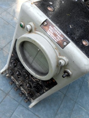
This question became a mini scope-shootout after a conversation with my Hackaday colleague [Elliot] about measuring oscilloscope bandwidth, and then my fellow Oxford Hackspace members producing more than one scope for comparison. You know who you are, thank you. I found myself with ready access to several roughly equivalent models and one very high-end one in specification terms representing different strata of test equipment manufacture, and with the means to examine their performance.
I thus had a chance to look at what the extra money secures in performance terms when you buy an instrument, and gain some idea of whether a more impressive badge is worth the outlay. So what follows is not quite a review of oscilloscopes because I’m not going to dive into feature comparisons, but an evaluation of the bandwidth performance of scopes from several different manufacturers.
Bandwidth vs Everything Else
You might think that what matters in a scope is its timebase; that its quickest setting will tell you how high a frequency it can display. And in a sense you’d be right, but if the scope’s internal electronics are only able to resolve a signal at 50 MHz, it doesn’t matter that the screen can trace out faster signals than that — it will just smear the same 50 MHz signal across more squares of its graticule. If you’re looking for wiggles at a higher frequency than that, they just won’t show up. A scope’s _bandwidth_, the highest frequency wiggles that it can resolve, is what we care about with respect to “speed”.
How does one measure the real bandwidth of an oscilloscope then? The simplest way is to give it a voltage transition so fast as to far exceed its capabilities, and measure the extent to which it has trouble catching up. If you feed it a rise time measured in picoseconds and count the nanoseconds of the rise time that it reports, there is a handy formula to derive the 3 dB bandwidth of its electronics from that figure.
Bandwidth (Hz) = 0.35 / measured rise time (S)
In practice it’s convenient to remember that for a rise time in ns the formula returns a bandwidth in GHz.
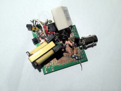
The fast rise times used for the tests in this article come from an avalanche relaxation oscillator following a design from [Kerry Wong], producing roughly 500ps rise time pulses. It uses the ubiquitous 2N3904 general-purpose NPN transistor, and since it requires well over 100V for the transistor to enter avalanche mode it incorporates a small switching inverter using parts scavenged from a scrap ATX power supply. The whole device is built dead-bug-style on the back of a surplus PCB from a prototype run, and connects to the scope with the shortest possible BNC lead. In this realm of measurement the slightest stray capacitance can cause a significant lengthening of the measured rise time.
To the Scopes!
The scopes I had for my tests were two older models, and three current ones. The older scopes were a Tektronix TDS210 80 MHz LCD model and a LeCroy LC584AXL 1GHz CRT model, while the current ones were a Hantek MSO5102D representing the lower end of the budget market, a 50 MHz Rigol DS1054z representing the upper end, and a 100 MHz Rigol MSO2102A from a slightly higher stratum. This DS1054z had not as far as we were aware had the famous software hack so was still a stock 50 MHz model, however no software hack changes the front end hardware.
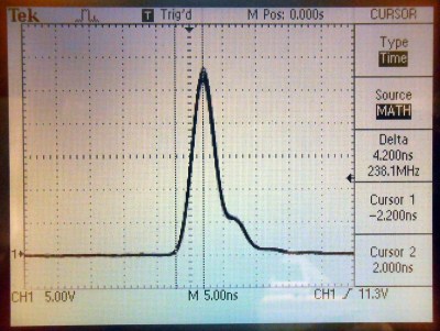
Looking at each scope in the order listed above, we’ll start with the Tektronix. This is very similar in appearance to the three newer scopes, being a lightweight portable LCD model. It’s evidently not the latest spec though, with a mono LCD screen, no USB connectivity and a parallel printer port. Thus its screenshot is a photograph.
The Tek’s measured rise time of 4.2 ns gives a calculated 3 dB bandwidth of 83.3 MHz, only just above the quoted bandwidth of the instrument. Some of this figure may be due to it having to be measured by manual cursor placement, looking again at the screenshot they could be closer to the 10% and 90% points.
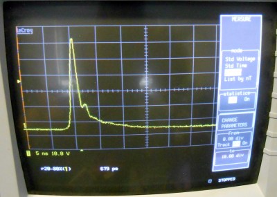
Moving to the LeCroy, yet again we have a photograph rather than a screenshot. This scope was very expensive when it was new in the 1990s, and it has a 1 GHz bandwidth, but it only sports a 1.44 Mb floppy drive and a thermal printer. Unfortunately we didn’t have a floppy disk, so out came the camera. With a rise time of 679 ps this instrument gave the fastest reading of all we tested, unsurprising given its quoted performance. If we were to feed this figure into the formula above we’d arrive at a 3 dB bandwidth of 515 MHz, so given that this is a 1 GHz scope we are measuring the rise time of the pulse itself. This was using the instrument’s internal 1 Mohm termination because of the voltages involved, its owner suggested that the full bandwidth might require use of its 50 ohm setting and we could thus still be seeing a bit of stretch. At these timings the most unexpected factors can make a significant difference.
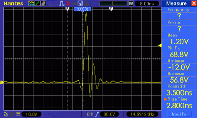
The modern trio of scopes are all much more up-to-date in their interfaces, with USB sockets below their colour LCD screens. The Hantek first, it gave a rise time of 2.8 ns, which corresponds to a 125 MHz bandwidth. This follows the trend set by the older model, a modest margin above its quoted bandwidth. This model is reputed to have a software hack that delivers a 200 MHz bandwidth, it’s fairly obvious given this measurement that such a figure would be illusory. In the screenshot you can see a little ringing after the pulse, this is due to the roughly 100 mm BNC lead we were using to couple pulse generator and scope.
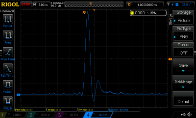
The Rigols completed our tests. The DS1054z first, with a 1.4 ns rise time. This gives the instrument a 3 dB bandwidth of 250 MHz, a significant surprise at five times the quoted bandwidth and over twice the bandwidth with the software hack. This scope also exhibited a bit of ringing, though less than the Hantek.
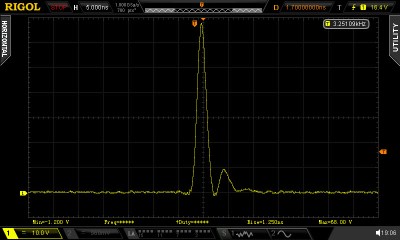
Finally in our selection of instruments came the Rigol MSO2102A. This had a rise time of 1.25 ns, which gave it a calculated 3 dB bandwidth of 280 MHz. Not far short of three times its 100 MHz quoted bandwidth, so yet again it has the same large bandwidth margin as its lower-range sibling.
It may be slightly unfair to compare two slightly long-in-the-tooth digital scopes to three very modern models, but it’s a worthwhile comparison when you consider the manufacturers. Brands like LeCroy and Tektronix are supposed to represent the high-quality end of the market, so we should expect their products to foreshadow the performance of their budget competitors by a decade or so. In particular the Tektronix is a directly equivalent model to the more recent trio in terms of form factor and quoted bandwidth. So in looking at these older models we are not so much looking at their performance compared to the newer ones in a negative sense, more looking to see how far the technology has evolved since their manufacture.
Putting all four models within the range of our pulse generator in a table to compare their figures, we see the following:
| Model | Quoted bandwidth | Measured rise time | Calculated 3 dB bandwidth | Percentage bandwidth overspecification |
|---|---|---|---|---|
| Tektronix TDS210 |
80 MHz | 4.2 ns | 83.3 MHz | 4.125% |
| Hantek MSO5102D |
100 MHz | 2.8 ns | 125 MHz | 25% |
| Rigol DS1054z |
50 MHz | 1.4 ns | 250 MHz | 400% |
| Rigol MSO2102A |
100 MHz | 1.25 ns | 280 MHz | 180% |
At this point it’s fairly obvious that the two Rigols give the most Bandwith Bang For Your Buck among the models tested, extending far beyond their quoted or even hackable bandwidth. Without opening up both instruments it’s impossible to tell, but would we find substantially the same front end chipset in all 200 MHz and below Rigol scopes? Meanwhile when you buy the Hantek you pay a very reasonable price depending where you look, and get exactly what you pay for.
The interesting story comes from the older model. The Tektronix has quite a narrow margin of bandwidth overspecification. This might seem odd for what would have been quite an expensive instrument in its day, but it’s worth considering that digital oscilloscopes were significantly more cutting-edge technology in those days than they are now. When you pay for a digital scope you are in a significant sense buying the quality of its analogue-to-digital converter, and given that ADCs of this speed were quite exotic pieces of silicon in the 1990s it’s hardly surprising that the designers at Tektronix had less margin available to them within the target budget for their product.
The process of choosing a scope and then investigating the performance of digital scopes over the past few weeks has been an extremely interesting one. When you have used these instruments for over 30 years you believe you know everything there is to know about them, but the work documented here has proved there is always something new to learn, and measure.


Damn no 3.5″ floppy? Upgrade from 5.25 already! :-D
a bit off topic, but I recently bought 300 floppies from ebay. Earlier this year I needed one and for the first time in 20 years I couldn’t find one. I figure with 299 floppies left over I’m set till armageddon.
Sell the rest on ebay?
The circle of life…
To Yamaha Keyboard users. They still buy floppy drives and disks.
http://www.ebay.com/itm/YAMAHA-W7-W5-SYNTHESIZER-KEYBOARD-REPLACEMENT-FLOPPY-DISK-DRIVE-NEW-/261719128903?hash=item3cefacfb47:m:mlAIa_kvfk8emlqOJawBn7w
This is why there are floppy drive emulators.
Here’s one that’s fully open, the schematics and source code are offered for a SD card model and one that operates directly tethered to a host PC. There’s also a port of the firmware to a similar device that uses a USB drive to store the floppy imates.
http://hxc2001.free.fr/floppy_drive_emulator/
we’ve got a shop here with floppies Verbatims box of x25 $14 they even sell CD-R
USB everything damn
“The interesting story comes from the older model. The Tektronix has quite a narrow margin of bandwidth overspecification.”
No, not really. First, the 4.2 ns rise time is obviously way too big: that’s much closer to a 0 to 100% risetime than 10-90, which would be something like 3V – 25V on that scale. It looks like it’s almost a quarter division (~1.25 ns) too big, which would give significantly higher measurement.
Plus, and probably more importantly: the TDS210 is a 60 MHz scope, not an 80 MHz scope.
Yeah, it’s definitely a risetime of around ~3 ns, or around ~117 MHz 3 dB bandwidth. (The fine tick marks are 1 V in voltage, and 1 ns in time, so the ‘MS Paint’ exercise of creating XY cursors is pretty easy). Since it’s a 60 MHz scope, that’s about double its specification, which seems like a nice healthy engineer’s margin to me.
As the owner of a TDS210 this is good news :)
Also, there is a serial port on the back too which you can use to dump the screenshot directly to a PC. I do it all the time and it works.
Nice to see there’s still fans of the TDS210 out there; I’ve got one sitting on my bench at work. Even though we’ve got some nice modern scopes, I still stick with the TDS as an every day scope.
Just one note though: be careful, as they were recalled as being dangerous.
http://www.tek.com/service/safety/tds210-tds220
I contacted Tek about mine earlier this year (S/N: B040019). They said if it was damaged that parts were no longer available (it wasn’t) but they would honour the upgrade: I sent it off to their repairer and it came back a few weeks ago with mod stickers and tamperproof seals on it; I won’t open it up to see what was actually done, but I was still amazed: they honoured a mod from 18 years ago!
At the time that Tek came out, it was a big deal for a ‘scope to be portable, and the use of an LCD was a necessary evil to achieve that goal.
Regarding Rigol front ends, I think I recall post(s) in the EEV forums where they’ve been compared. As I’m lazy and searching EEV forums is hard, I’ll leave it as an exercise for the interested reader.
According to this.. http://web.mst.edu/~cottrell/ME240/Resources/Inst_manuals/TDS210%20quickguide.pdf
It’s supposed to do 1 Gigasample per second, so I’m wondering if it was tested with the bandwidth limit enabled.
You’re confusing analog and digital bandwidth. What they were trying to measure here was the analog bandwidth of the front end of the scope. After that comes the ADC, at which point the 1G sample/s number becomes relevant. If it takes the scope 4ns to respond to the pulse in the analog domain then it doesn’t matter what the sample rate is above about 175M samples/s
Right, but at that point the scope was designed, I believe the digital part was the spendier part of the equation, so freaking odd that it’s 5 times better than the front end lets it be. Hence, I was wondering if the BW limit was implemented by switching in a smoothing cap in the front end, which the 4ns is the rise time of.
The front end’s about ~120 MHz. Sampling’s 8 times that, but that’s *total* sampling. Both channels at the same time means 500 MSa/s, which means it’s really only about 4x higher than 3 dB point of the front end.
That doesn’t sound like overkill at all. You need an antialiasing filter at 250 MHz anyway.
If I remember correctly, the TDS2xx series (and TDS2xxxx, which were slightly later with color LCD and more math functions) were essentially first DSOs that could be used as meaningful replacement for traditional CRT scopes. In my opinion there were three reasons for that: sampling frequency that was significantly higher than analog BW (and thus lower probability of aliasing and other DSO artifacts), compactness and for the time reasonable price. I assume that all these three features largely come from the fact that these scopes internally contain three Tek ASICs, m68k and nothing much more.
Interesting how some scopes saw ringing and others do not. Was the signal ringing, or wasn’t it? In either case, some scopes are showing the truth, and others are lying.
I use to work for Agilent (now Keysight), and worked on one of the “Mega-Zoom” ASICs. I can tell you that they guys designing those things care a LOT about making sure that the scope shows you what is really going on, and would take it as a personal failure if the waveform does not match reality. An Agilent scope, when used with Agilent probes, will not show ringing where none exists. I would also tend to trust Tek and LeCroy too, as they have a big reputation to live up to. With both of those showing no ringing, I am pretty sure that no ringing was actually happening. For the Rigols, it could be something like parasitics on the probe, an analog problem with the front end, or maybe some bad or non-existent DSP.
However, problems like this are why it is sometimes worth it to get a better name brand in test equipment (if you can afford it).
Without any details in the setups, I think it’s hard to figure out what is real and what isn’t. All the scopes look like they’re 1 Meg terminated, so they might see quite a lot of reflections (not terribly likely that the pulse is a nice 50 ohms anyway). Add a little bit more cable between the pulse and the scope and you go from what the LeCroy/Tek scopes see to what the Rigol scopes see.
The Hantek’s measurement looks really screwed up. It’s not even close: it looks more like an AC coupled measurement rather than the others.
If you take the LeCroy waveform as the ‘true’, really, the Tek is the only one that looks accurate, but again, without knowing setup differences, who knows.
I was rather assuming that the user was just using the included probes and touching them to the DUT. If this is the case, my statement still stands, as long as the manufacturer’s probes are used.
If, instead, the test setup included running raw BNC cables to the scopes, then my statement still stands, assuming that the same setup, including cables, was used for all scopes, and that the scope was set to proper termination.
In either case, a scope should do its best to not actually affect the test results. Yes, it is possible for a test setup to induce ringing, but it is curious that the big brands did not do this.
“If, instead, the test setup included running raw BNC cables to the scopes”
Yeah, that’s what it says they did. “due to the roughly 100 mm BNC lead we were using to couple pulse generator and scope.” You wouldn’t want to use a probe to measure the scope’s front end.
I have to think they must’ve switched cables at some point (to one 2-3 times as long) or something. Otherwise I can’t possibly see how you go from the Tek scope results to the Rigol scope results. The Hantek scope really looks like it’s AC coupled.
“Yes, it is possible for a test setup to induce ringing, but it is curious that the big brands did not do this.”
Yes they did. That’s the little peak you see shortly after the first peak. On the MSO2102A it’s the same thing, just more separated in time for some reason. I can’t imagine you have ~4-5″ of cable inside the scope itself before the termination, so I have to think it was a longer cable. Would also fit with the slightly lower peak (more cable loss).
The DS1054z looks quite a bit more questionable. I’m wondering, since it’s a software hack, whether or not you really need to recalibrate at the higher frequencies somehow. Both the DS1054z and the Hantek have pretty noticeable acausal behavior (the pulse *dips* before it rises) which you can imagine would be coming from an improperly applied equalizing filter or something.
The MSO2102A also has it if you stare really close, but it’s probably within Rigol’s calibration details. Neither the Tek nor the LeCroy show any evidence of acausal behavior whatsoever – that’s what money gets you.
All measurements exactly the same setup, the pulse gen, the 100mm BNC lead, DC coupled, 1Mohm input impedance.
Then there’s something screwy with the Rigol/Hantek scopes. They don’t match the expected waveform at all. Rise time is meaningless with that much phase distortion.
> Both the DS1054z and the Hantek have pretty noticeable acausal behavior (the pulse *dips* before it rises) which you can imagine would be coming from an improperly applied equalizing filter or something.
That will be the sin(x)/x representation (interpolation). Unfortunately one cannot turn it off in the Rigol DS1054z at short periods.
You called it, the bottom left corner of the Hantek image says “AC”, so it was AC coupled.
Do any of the scopes support active probes? I have a Keysight MSOX-2024A and that is probably the only feature that would cause me to eventually upgrade to a 3K series. When doing any real analysis on signals > 100 MHz, it is almost a must.
Funny, right around the time of your other article I was looking for a new scope for my dad and myself.. wanted battery + 4 channels.
Got the same Rigol DS1054Z you got and the Owon SDS7102 as well.
Both are nice units and have different pros and cons, the display on the Owon is gorgeous btw. – good for older people with glasses.
Too bad their 4 chan + battery XDS… wasn’t out yet, maybe in a couple of years.
Anyhow, it’s more than one guy here that’s using them, so I think we’ll do well with two units.
PS: the Owon got hacked already. Battery charging part of the PSU get’s unnecessarily hot due to undersized cap and no airflow. Both points got addressed by replacing the cap with 5 in series, moving parts of the low voltage circuitry to the underside of the PSU board to get enough space between the backside of the chassis and the PSU for another 6010 fan. Forgot to take pictures and all assembled already, but waiting on 5V ball bearing fans now and some mesh, so would have some chance to make them in 2-3 weeks time when parts are here – real pita to open that case.
5 caps in parallel, not series. little brain-f**t there.
Thanks, you had me worried there…
Interesting review, looked at this ages ago but didnt “upgrade”…
Still have a pair of HP 1631A/D and a couple of others which I got after I had an HP1742A with the DMM which died
as the HP analog asic went way out of kilter :-(
Those 1631’s though very solid & sit atop an HP 6264B – in need of its resistors being replaced, mildly
hygroscopic after how many decades ?
Thanks
And I got a battered Leader LCD-100 for a scope. 200 kHz of bandwidth.
What, no tests for 2 MHz Cossor? I’m shocked! :)
Without any attention to impedance matching, termination, transmission lines, the compensation network inside the ‘scope probe, and the kinds of connectors and probes that are used, it’s largely meaningless to simply compare different ‘scopes for their performance in this kind of high-speed scenario.
Wires aren’t wires. Wires are not simply some perfect, abstract, one-size-fits-all thing you don’t have to think about.
That’s basically the first elementary lesson of high-speed EE.
(Fast digital, or microwave RF – it’s much the same thing really, all the physics is the same, it’s just a Fourier transform between friends. So whether you like analog or digital all the basic considerations are applicable across the board.)
This recent series of “high-speed” articles does have the potential to be great, but you should start with the “wires aren’t wires” issue and an understanding of high-speed transmission line behavior as the first point, not as an afterthought to be largely ignored.
The pulse generator is kinda-sorta impedance matched. It’s back terminated with 50 ohms, and the source impedance of the transistor can basically be considered zero.
However, the problem here is that the scopes *weren’t* terminated, which means that you’re seeing a bounce off of the scope, then back to the pulse generator, and a small bounce back off because the 50 ohms isn’t perfect. Looking at the reflection in the LeCroy and Tek scopes, it looks like about ~20% of the original, which would imply a VSWR of around ~1.5, so not a terrible match. Not surprising either considering it looks like it’s a through-hole resistor.
If the cable was actually a little longer, then it really wouldn’t matter that much. Of course, with a longer cable, you’re rolling off the higher frequencies a little more, so the risetime will drop correspondingly. Don’t use cheap cable, and a 1-foot cable won’t be a big deal. The reflection looks like about the right spot for a 100 mm cable (~1 ns later).
The problem I have is with the Rigols (the Hantek’s just looks screwed up, so dropping that). There, the reflection comes *much* later: almost 5 ns! Where’s the signal being stored for that amount of time? Is the author *sure* that the same cables were being used there? Were the Rigol scopes 50 ohm terminated? (In which case, what the heck is that pulse?)
All measurements used the same setup, pulse gen, 100mm BNC lead, DC coupled, 1Mohm impedance.
You really do need to terminate properly; that will significantly affect the results. At 100MHz you ca get away with a BNC T connector and a 50ohm load. Higher frequencies benefit from an in-scope 50ohm or through terminator.
In addition the frequency response of the cable will affect results a little with a 100MHz scope; direct attachment to the scope’s input is preferred.
I *strongly* recommend you do a simple spice (e.g. LTSpice) simulation of a 100mm ideal transmission line terminated with 1Mohm//20pF, terminated in 50 ohms, and terminated in 50ohms//20pF. For a 100MHz scope and waveform, do an AC sweep from 10MHz to 1GHz. Also do a transient response.
I think you will be surprised at the results.
“You really do need to terminate properly; that will significantly affect the results.”
It’s back-terminated, and the probe’s high impedance. It just adds a reflection off of the imperfect back-termination. Terminating it well at the scope would help reduce that reflection by another factor of 10, assuming a 20 dB return loss.
“In addition the frequency response of the cable will affect results a little with a 100MHz scope”
4 inches of cheapo RG58 at 100 MHz is 0.014 dB loss. Even 2 feet would only be ~0.2 dB up through 500 MHz.
“direct attachment to the scope’s input is preferred.”
Direct attachment to the scope means the pulse and its reflection interfere, which means you get ripples in the frequency response. Now, granted, with 30+ dB of attenuation between the pulse and its reflection (assuming better than 15 dB S22 at the pulse generator and better than 15 dB S11 at the termination) the ripples will be small, but there’s a good chance you’ll still see them if the scope is good enough. Granted, most scopes are only 8 bits or less, so you might not have enough dynamic range to see them. But, well, good to get in the habit if you end up working with higher-fidelity systems.
Use a decent length of good cable (~6 feet of LMR-400, should be like $20-30, minimal loss even at 1 GHz), and then window the scope measurement around the pulse before you do the FFT to get the frequency response, and you’ll get a very clean measurement.
Sorry, you’re wrong. The screen shot of the Hantek clearly shows that it’s AC coupled (bottom left corner).
Also, the LeCroy measures the rise time from 20 to 80% while you measured something like 5 to 100% on the Tektronix. Which percentages the other scopes use is a mystery as of now. That means the numbers aren’t directly comparable.
On top of that, the Tektronix is a 60MHz scope, not 80MHz.
Very true, my mistake on the Hantek. TBH the Hantek doesn’t have the easiest interface to use, a more pertinent reason IMO not to buy it.
An easy mistake to make; “all knobs and buttons” interfaces have the advantage that nothing is buried deep inside menus, and that a quick scan with _peripheral_ vision can allow mistakes to be spotted.
Thanks Pat!
All those years of using 50 ohm terminators and I didn’t understand their purpose.
Interesting article. I’m surprised you got such a clean pulse. I’ll have to look at building one of those. There is one other important spec, flatness of response.
I’d like to suggest collecting a bunch of trace samples from the new scopes, computing single pulse FFTs with Octave and then averaging the FFTs. That will keep you from being mislead by variations in the pulses and the repetition rate of the pulses. Variations will be suppressed by 1/sqrt(n), so it will give you a good estimate of the spectrum. Then compare the FFT profiles to the scope specs. The manufacturing issue may be achieving flat response across the full bandwidth. This would be a particularly interesting comparison on the Rigols. If the DS1054Z has a deviation above 50 MHz that exceeds the spec, that would tend to confirm my suspicion that the labeling is based on production final test results. Another useful thing would be to do the tests using two different length cables in case there’s an impedance mismatch e.g. at the scope end of the Hantek.
“This model is reputed to have a software hack that delivers a 200 MHz bandwidth, it’s fairly obvious given this measurement that such a figure would be illusory.”
No. After the hack, the Hantek DSO/MSO5000 series will have a 1.8ns rise time, which gets you close to the 200 MHz bandwidth rating of the DSO/MSO5202. The manufacturers use more than one approach to unlocking bandwidth, so the results WILL vary.
Also, as a suggestion, avoid the use of the word ‘obvious’ in articles like this.
All this about about hundreds of MHz and here I am, happily rocking my 200KHz dso138 oscilloscope!
Well, there’s that :-) Kinda like Horsepower you may never use.
For audio amplifiers, 200KHz is all you need. My dad uses an old HP analog 200k scope that has a differential input mode for measuring things w/o a ground reference.
Tbh, I’m not interested in audio-stuff at all. I just can’t afford a “real” scope, so I make do with what I have.
Hmmh, analogue-only CRT scopes (“CRO”) with a band width of less than 100MHz are now dirt cheap on the used market. Even fancier, faster ones can be had for a song. Craigslist SF Bay Area has currently a 275MHz HP1725A for $125 (might need some TLC) and a fine Tektronix 485 (350MHz) for $275 (I’m tempted myself).
Kinda like the $40 multimeter vs the $400 multimeter. My DSO Nano is also 200 kHz, and it’s all I can afford…
If a 200kHz scope is sufficient for your application, then it is an elegant use of appropriate technology. I’ve no time for people that brag about driving to a supermarket to get a loaf of bread in a Ferrari.
Exactly, my kids need enough to learn, and as little expense as possible to maximise the number of tools they we can afford to teach them to use.
I think any fully transparent comparison would look at scopes across price ranges, or even just try to plot price vs performance.
The people in our TJ factory bought some Rigols in early 2015 for troubleshooting stuff on the production line – three of seven are now dead. Shipped them some 15 to 20 year old Tek and HP/Agilent scopes sitting on our shelves, and the first thing they noticed was the difference in waveform shape and other artifacts of dynamic bandwidth.
Meh. There is a reason some stuff costs much less…
Mathematically the scope trace is the convolution of the input waveform and the scope’s (inc probe) response. If the input waveform is an impulse, then the trace will be the scope’s impulse response – and the risetime can trivially be calculated from that. But in this case it isn’t an impulse; the input waveform is undefined (albeit fast) and hence the scope’s impulse response and risetime *cannot* be determined from the traces.
The most practical way of determining the risetime is for the input waveform to be a step, with a risetime greater than that of the scope.
As a separate issue, the cabling and termination are vitally important when making measurements such as these. Without specifying those details, the traces are of unknown value.
As an example of the latter, consider that a typical probe has an input capacitance of 15pF. At 100MHz that is a (reactive) impedance of 100ohms (20ohms at 500MHz). That is very significant compared with even a 50ohm source – and the source’s impedance is actually undefined.
“the input waveform is undefined (albeit fast) and hence the scope’s impulse response and risetime *cannot* be determined from the traces.”
If it wasn’t for the reflection, you could basically do it. Look at the Rigol traces – they’re fairly symmetric rise/fall. Look at the link for the pulse generator and you’ll see that it’s pretty much just a band-limited impulse, which means the FFT gives you the frequency response of the scope.
As I said above, the big problem with the measurements here is the 1 Meg input impedance. The author really needs to remake the measurement using a BNC tee + a discrete 50 ohm termination, still using the 1 Meg input impedance on the scope (so the scope becomes a stub, but it’s a high impedance stub, and it’s short. Under a GHz or so, it’s not going to be that bad).
“That is very significant compared with even a 50ohm source – and the source’s impedance is actually undefined.”
No, it isn’t. The source is back terminated with 50 ohms. Take a look at the link for the pulse generator and you’ll see that when it’s plugged into a 50 ohm load, it’s a clean pulse.
Symmetry is irrelevant. Consider an unknown filter, where you can see the filter’s output but not the filter’s input. What is the filter’s frequency response? Obviously you have insufficient information. Now realise the scope is such a filter, and that the input waveform isn’t known. Hence you cannot determine the scope’s characteristics. OTOH, if the input is a step with a risetime < the scope's risetime, then determining the scope's risetime is trivial.
As for the scope's input capacitance being significant… Just do a spice simulation, and you will see that it can be very significant – for the reason I stated. Or ask any radio ham to show you how to use a Smith chart. Or even just read at the scope's VSWR specification!
Practically, even on my 1970s 400MHz scope I can clearly see the effect a 20pF input capacitance has on a waveform coming from a 50ohm source and terminated in a 50ohm load – and it matches the spice simulation!
No. The symmetry means everything, because now it’s just a pair of step functions, with both the odd and even harmonics – in other words, if it was a pair of infinitely fast steps, it’s now an impulse, which has equal frequency content up to the bandwidth limit, and you can actually just take the FFT to get the frequency response of the scope. With a ~500 ps rise and fall time, it’s going to be flat up to several hundred MHz, if it wasn’t for the reflections.
The reason you just use the risetime with a step function is that you can work out what the 3 dB point is from it. But an impulse gives you the entire frequency content straight off, and this pulse *is* an impulse. I’ve used impulses like this to get frequency responses all the time.
“As for the scope’s input capacitance being significant…”
You’re *trying to measure* the response of the scope. Of course the scope’s response is significant.
As someone barely out of scope noob-hood (I’ve mostly gotten by without needing one, and spend more time with the spec an than with the o-scope), I find this discussion informative and fascinating. Thank you both for your back and forth. Do either of you have (a) recommended print resource(s) for someone wanting to really learn the proper methods and theory of scope operation? I know I need to fill in the (numerous) gaps around my basic scope knowledge, and you both seem like people who could point to really good resources on the subject! Thank you!
Pretty sure the “software hacks” are generally switching a cap in/out of the filter. For example, on the rigol 1052E, when you twiddle the bits to make it think it’s an 1102, you get 100MHz bandwidth, and can see faster rise times. The sample rate doesn’t actually change, You’re just raising the cutoff of the filter. You can probably get the same result in hardware by removing/swapping the capacitor. Of course with the hardware hack alone, your timebase might still be limited, assuming it’s different between the scopes (I beleive it is on the 1052E, don’t know about others).
It needs to be limited to avoid aliasing, but they intentionally further limit it to allow them to sell the same hardware at different levels, and to allow paid upgrades, etc.
It is more likely that the software change merely changes DSP filter coefficients. I’m sure other people have done a proper investigation of that; eevblog would be a good place to start looking, since some of the threads there discuss the front-end in detail.
It’s in the hardware. Skip to 31:40 in Dave’s reverse engineering video here:
https://www.youtube.com/watch?v=lJVrTV_BeGg
I stand corrected.
It looks like they are using an RC rolloff rather than the ideal Bessel filter rolloff (Bessel filter => linear phase => minimal pulse shape distortion). I was assuming they were using a higher sampling frequency plus a DSP filter to approximate a Bessel filter.
Without having considered it in detail, might the RC rolloff be a cause of “Pat says: October 5, 2016 at 6:20 pm Then there’s something screwy with the Rigol/Hantek scopes. They don’t match the expected waveform at all. Rise time is meaningless with that much phase distortion”?
Really? Again with this fast pulse “measurement” thing? Now I know this is Benchoff in disguise. Only he is the master of writing articles about stuff he doesn’t understand. And seriously quit pushing your ugly circuit board thing. This is 3 times now. Get a real board made.
Instrumenting and measuring fast signals is serious business. Just because you get a trace on your scope doesn’t mean you can know anything about that signal or the scope measuring it.
“At these timings the most unexpected factors can make a significant difference.”
Ya think? You don’t have to guess. How about reading up on high frequency measurement and THEN come back and write an article… maybe then things won’t be so.. unexpected.
Again… Here is a link to someone who knows what he’s talking about..
http://www.siliconvalleygarage.com/projects/picosecond-pulser.html
The “ugly circuit board” thing is probably a red herring. Have a look at how people such as Jim Williams construct boards; read his justly famous “AN-47”.
The Jim Williams prototype stuff was ugly too.
Beauty is in an expertly laid out board that is at the same time functional, reliable, and reproducible.
Beauty is in the eye of the beholder, and to my eye Jim William’s boards were works of art. Were he alive to comment I’m guessing he’d disagree out of modesty, but don’t knock stuff for looking unpolished. He did it the way he did it for a reason, and he had a knack for knowing what would work how it needed to work when he built those prototypes.
gaah… need an edit button… * Williams’ * not * William’s *. Forgive me, fellow grammar pedants.
The Real Art in the Jim Williams stuff was in the circuit design. There is an aspect of art in his prototype builds, but only in that he understood the limits of that medium and how to work with and around them. The hackaday ugly pulse thing board is just a mess on an old scraped up scrap PCB.
That’s absolutely beautiful.
(Although, in fairness, the neat PCB has the output transistor region where it really matters basically reverting back to very careful, clean Manhattan-like construction.)
These are the kinds of factors that matter. If you put too much solder on the SMA pin you’re going to get an impedance mismatch and you’re going to see a little bit of that pulse bounce off that solder joint.
Time it well enough, and you can find exactly when – therefore exactly where – your cable or connector fault exists that is causing the reflection. And hence we get into time-domain reflectometry.
If you like this thread, go and get all the details straight from the source – go and read Jim Williams’ AN72, where he describes this design, how it’s used, why it’s used.
I highly recommend reading this – but surprisingly neither of these recent HAD posts have mentioned it.
http://cds.linear.com/docs/en/application-note/an72f.pdf
As far as fast scopes are concerned, you may pay hundreds of thousands of dollars for the latest 100GHz dick-measuring-contest scopes from Agilent or Lecroy today, but I have a lot of respect for the Tek 519.
45 kilos of aluminium, 650 watts, a pinch of Maxwell’s equations and elegance.
And most of the rest is vacuum.
Rise time of about a couple hundred picoseconds.
Designed around the time of Sputnik.
http://www.timkoeth.com/?cat=5
http://w140.com/tekwiki/wiki/519
If you look at the schematic it’s also a neat practical example of an avalanche pulse generator.
There were no cheap commodity GaAs HEMTs or modern ECL from DigiKey back then :)
There are several guidelines for the bandwidth rule of thumb used, it only applies to first order filter approximations, it is for a step signal rise time not an impulse, is approximately +/-10% of reading. There is a IEEE spec for measuring scope bandwidth IEEE 1057-2007. Metrology is a deceptive subject.
These Hantek oscilloscopes worked super well for us. It’s also nice because their tech support was able to help us with setup bit.ly/digital-oscilloscopes
I have just perform the same test on my rigol ds1054z and I get a rise time of 1,1-1.2ns