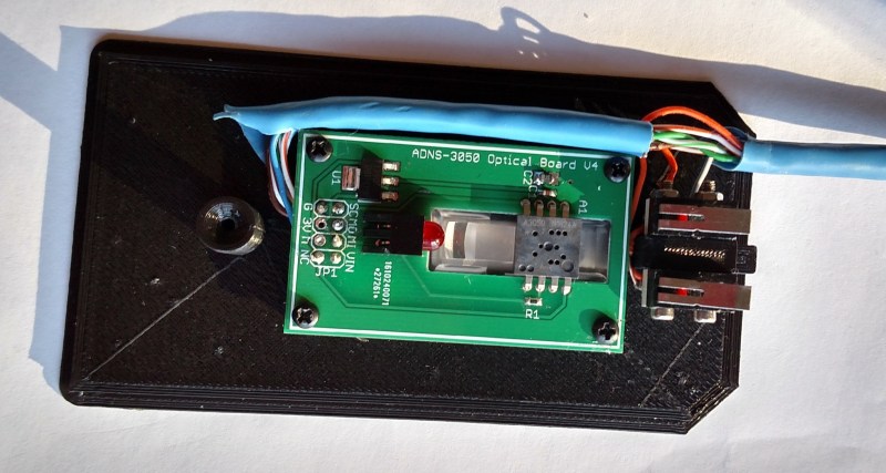
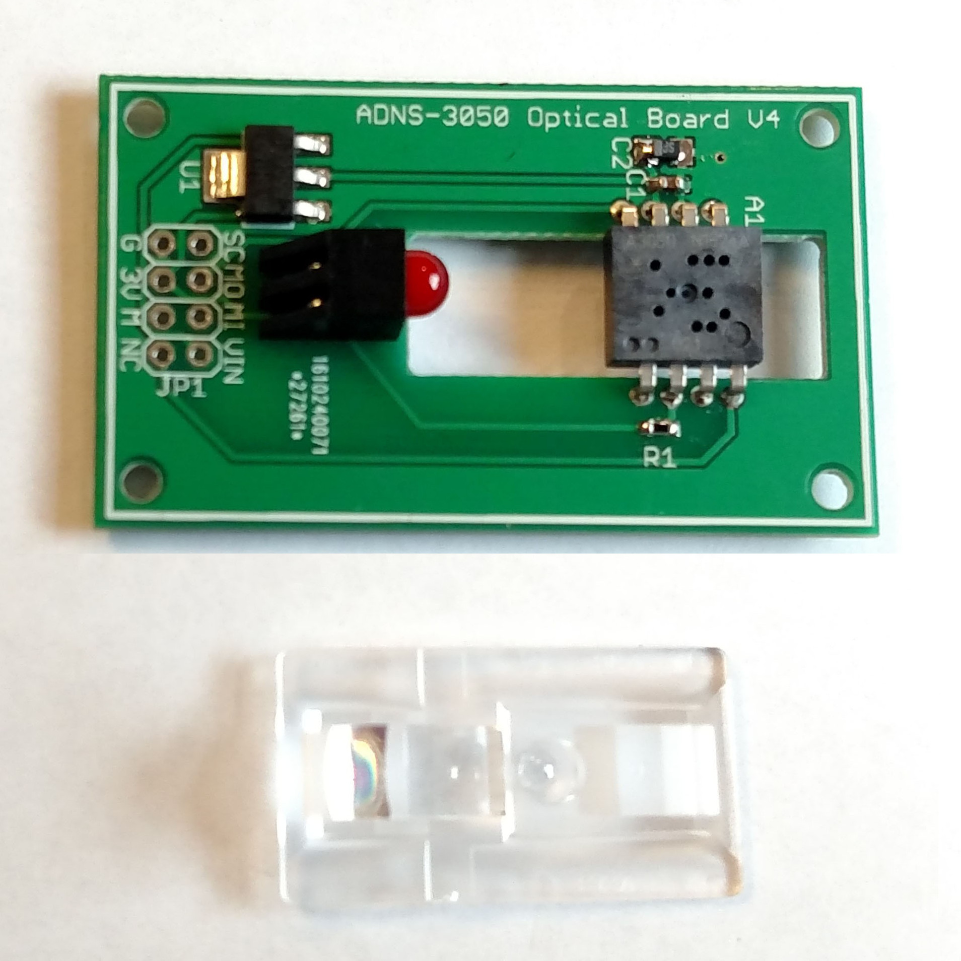
Wanting to experiment with using optical mouse sensors but a bit frustrated with the lack of options, [Tom Wiggins] rolled his own breakout board for the ADNS 3050 optical mouse sensor and in the process of developing it used it to make his own 3D-printed optical mouse. Optical mouse sensors are essentially self-contained cameras that track movement and make it available to a host. To work properly, the sensor needs a lens assembly and appropriate illumination, both of which mate to a specialized bracket along with the sensor. [Tom] found a replacement for the original ADNS LED but still couldn’t find the sensor bracket anywhere, so he designed his own.
 The github repository contains all the design files as well as Arduino libraries. Thinking others might share his interest in an easy to use breakout board for the ADNS 3050 that doubles as the mounting bracket, [Tom] started a Kickstarter campaign for a small production run.
Optical mouse sensors have often shown up as experimental movement trackers in hobby robotics, and even as low-res cameras. There’s a lot going on in these little packages and [Tom]’s fully documented open-source design tries to make it more accessible.


All of these guys (in any related series, too!) seem to be obsolete or discontinued at digikey. Any idea what parts should be used to take their places?
Ever since Pixart took over Avagos mouse sensor division parts have been scarce if you weren’t a manufacturer. The new PMW3325 sensor looks interesting but I can’t find it anywhere as of right now. Pixart have mostly ignored my contact requests too. I found a company in china that still stocks the ADNS 3050 and that’s where I’ve been sourcing my sensors right now.
That’s really depressing.
If I could get my hands on some of the higher end ones, do you think there would be a market? I am kind of a distributor for espressif ATM :-p. I could do more.
We use the highest end mouse sensors as part of a position tracking system. They are very useful!
I’ve been hunting sensors for a long time, and either the documentation was unavailable, or the parts were in quantities less than 200. My specific requirements are available documentation and pixel-matrix readout capabilities. Other than that any sensor assembly (w. LED and lens) would suffice, high end ones would be more than what I need, but I’d take what I can.
I have the entire datasheet for the 3050 on my GitHub here if you are interested : https://github.com/Tom101222/Adns-3050-Optical-Sensor
The sensor CAN output the individual pixel information aswell
Seriously. I wanted to use one in a project a few years ago but could never find one.
Maybe I should try alibaba or aliexpress.
That’s where I found my supplier, shipping is astronomical for samples though :( I added an option for just the sensor and the lens to my kickstarter for anyone interested.
Let me know what you find.
These are extremely interesting devices, and some of them have very high resolutions. I’ve made a few dev boards with these for various purposes, you don’t need to make specifically a mouse. You can point them at the filament on your printer, or cut an acrylic wheel and sandpaper the edge and mount one to watch the edge of the wheel as it rotates.
Lots and lots of resolution this way. Some of the chips have thousands of points per inch. They’re very easy to program/interface to.
would linear encoders be possible with this? for example, for a 3d printer or other cnc applications?
Yes.
Depending on the surface finish of your rods, it could read distance directly from one of the support rods. If the rod is too “uniform” in appearance it won’t work as well, but you can do things like add bluing or go over it with a sharpie to make a more specular surface.
This would reduce the travel distance by the width of the sensor, so you could mount an extra rod parallel to the support rods that isn’t used for support, you can make it out of something more specular and have the sensor look at that.
Take an acrylic rod and sand the outsides until it looks frosty, or similar.
I also found that an optical mouse makes a good prototyping board outright. Take a pair of side-cutters and cut out the DIP micro controlling the optical sensor, and replace the pins with headers. Power, ground, and SPI lines going to the sensor have to also go to the micro, so just find these by looking up the sensor datasheet online.
See here for images.
https://hackaday.io/project/5283-potpourri/log/49337-optical-flow-sensor-from-an-led-mouse
I could even give you the arduino code, but you probably couldn’t use it. It’s not a sketch, it runs on the bare micro :-). (I have a ton of shelved projects like this.)
Also, using an optical mouse directly isn’t terribly difficult. On Windows you grab a copy of LibUSB and make a driver specific to the PID/VID of the mouse that doesn’t attach as a regular mouse. Then you can open the raw device from a program and get the X/Y displacement directly.
I haven’t done this yet on linux, but there it’s probably even easier.
nice, thanks! i’ve been trying to find a “cheaper way” for linear encoding.
I fount the rubber page grabbers from gutted inkjet printers work great for pickup services. I would use reflective tape and stripe it for DIY shitty reflective encoders. Now that I can get a mouse on Amazon for $3 why not do it this way all the time!
Take a look at the PMT9123. It’s made for that purpose: “compact tracking system that does not require code wheel, code strip many any special marking on the tracking surfaces for motion control or tracking purposes”. The non-NDA datasheet available on the Pixart site has a datasheet that’s sufficiently complete to figure everything out that would be needed for an Arduino library. 25ips at accelerations of up to 8g also seems like enough for most 3d printers.
If there is enough interest in this sensor, let me know and I will talk to my contact at Pixart and my distributor about pricing and start a group get. So please leave a comment here or on my hackaday.io project: https://hackaday.io/project/18467-optical-tracking-sensor
i would need like 20 of these sensors.
I already sent a RFQ to my distributor. Once I get a response, I’ll update the project page.
preferably with a breakout board
Take a look at the project page ;) Breakout board is done, still waiting for the quote, though.
Digital Calipers use a pretty accurate capacitive sensor.
Mice are way cheaper to have though. But you make me wonder if you can get the digital caliper components without the caliper. I imagine the metal is a good part of the price.
yes IF you talk directly to the sensor AND have full documentation.
Those sensors have tons of customizable parameters like smoothing, negative acceleration and interpolation. they are NOT linear in 99% of mouse usage scenarios.
https://www.youtube.com/watch?v=CIRKRzw54Zs
How well do you think an optical mouse sensor like this would track as a rotary encoder on a telescope’s azimuth bearing? High CPS rotary encoders are damn expensive but a hacked up mouse with 2000dpi on an 8″ bearing is like 16,000CPR.
See my response above. It should work.
Note that some of the optical flow sensors have an incredible resolution, something like 4096 points per inch for some of the gaming sensor chips.
Hmmm, wonder if this would make a good foundation for a 3D printer?
What about a camera and a series of QR codes? Read the QR code to determine which segment it’s on and the position to get the exact offset. That has the advantage of absolute position sensing.
A properly implemented optical encoder does that.
Obviously I wasn’t the first person to have this idea… :)
I’ve heard that the repeatability on these sensors isn’t great. However, most sensors of this type can also output raw “camera” data. My thought was that you could print a strip of paper with a non-repeating pattern and wrap it around the azimuth bearing, then use the raw camera data with a simple computer vision algorithm to detect absolute position on the strip. (Similar to the way those fancy Livescribe pens work.) Since camera data readout is slow on these sensors you could use the sensor’s less accurate relative positioning to get a rough estimate of where you were on the strip, then read the camera data when the position was no longer changing to get an absolute fix.
While these sensors go up to “2000 cpi”, I believe the imaging array is actually a fixed size, and the cpi setting just multiplies the counts it gets from the array, so you’re not actually getting any more accurate readings… But still, at the sensor’s native 1000cpi, if you ran this sensor around the outside of an 8″ disc, you’d be getting around 25,000CPR, which is up there with the best rotary encoders. That would give you about a 50 arcsecond step, which would be overkill for most wide field scopes.
I’ve been trying to figure out how to make this work with my GSO SkyView.
(On a side note, as [uminded] mentioned, if you think these sensors are hard to get, try finding the high-resolution 30k CPR rotary optical encoders they use on telescope mounts. They seem to be only manufactured for and sold to telescope mount manufacturers, who mark them up to around $100 apiece. The market is ripe for disruption.)
Saw in the datasheet that the 3050 also has register values for the minimum and maximum and average. That’s sort of handy in regards to the issue of reading out all pixels and the evaluating since you have a quicker alternative way of getting some essentials.
PIX_MAX
Data Type: Eight-bit number.
USAGE: Store the highest pixel value in current frame. Minimum value = 0, maximum value = 254.
The highest pixel value may vary with different frame.
PIX_ACCUM
Data Type: High 8-bits of an unsigned 17-bit integer.
USAGE: This register stores the accumulated pixel value of the last image taken. This register can be used to find the average pixel value, where Average Pixel = (register value AP[7:0])* 1.058
The maximum accumulated value is 122936 but only bits [16:9] are reported, therefore the maximum register
value is 240. The minimum is 0. The PIX_ACCUM value may vary with different frame.
PIX_MIN
Data Type: Eight-bit number.
USAGE: Store the lowest pixel value in current frame. Minimum value = 0, maximum value = 254.
The minimum pixel value may vary with different frame
It remembers me a retrofit made in an 80’s mouse:
http://www.msxpro.com/tpx_retrofit.html
For those who don’t want to wait until February, I found this breakout board: https://www.tindie.com/products/jkicklighter/adns-9800-laser-motion-sensor/
Different chip, but a similar product.
That said, I backed your Kickstarter project because we need more of these types of boards in the world.
Could a CD/DVD and drive be used as a high resolution rotary sensor? Of course they could, but I haven’t the slightest idea how to do it.
Or maybe even as a super high res optical mouse! LaserDisc mousepad maybe!?
If anyone has any great links on how to do this, probably in software…
…or standalone firmware-hacked USB input device.
That seems entirely impractical when you have these mouse sensors available. A laser assembly of a CD/DVD drive seems a bit cumbersome and fiddly in comparison, and would require a complex own solution for evaluation whereas a mouse sensor has it all in a simple small and intelligent package.
Although it’s true that there are people who are hellbent on doing things the hardest way possible.
You’d need several… Its basically a 1D sensor that already knows which direction it’s moving, so like half a D really.
I’ve always wanted two of these on a board to mouse around and then you could track rotation too.
Hi everyone, I went and did a smaller production run than anticipated so the boards are now available on tindie!
https://www.tindie.com/products/tom10122/adns-3050-sensor-board/
Cheap, accurate digitizer for small mechanical xy stage.
Build your digitizer this way:
– take a smartphone with a hd display
– draw a grid on the screen
– place the optical mouse sensor on the screen
– get xy coordinates from sensor
Calibrate by moving the grid a few pixels while keeping the mouse sensor stationary, and seeing how much the sensor thinks it moved.
A oldish 5.5″ smartphone screen has 1440×2560, 538 pixels per inch. So if your mechanical stage is more or less the size of an lcd screen, you’re in luck.