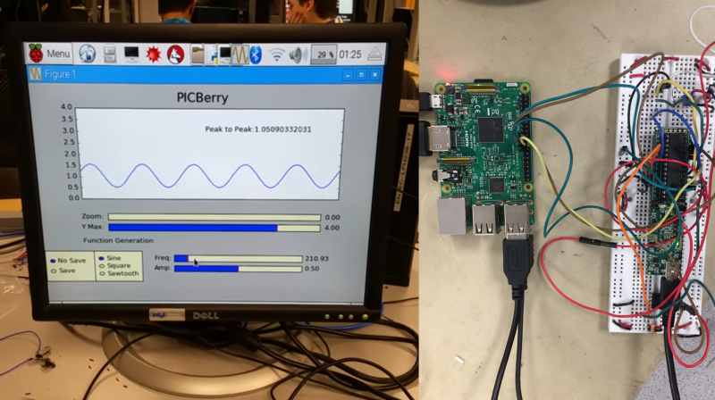
The PicBerry is a student final project by [Advitya], [Jeff], and [Danna] that takes a hybrid approach to creating a portable (and affordable) combination digital oscilloscope and function generator. It’s based on the Raspberry Pi, features an intuitive Python GUI, and can generate and measure simultaneously.
But wait! The Raspberry Pi is a capable little Linux machine, but meeting real-time deadlines isn’t its strong suit. That’s where the hybrid approach comes in. The Pi takes care of the user interface and other goodies, and a PIC32 over SPI is used for 1 MHz sampling and running a DAC at 500 kHz. The idea of combining them into PicBerry is to get the best of both worlds, with the Pi and PIC32 each doing what they are best at. The readings are sent in batches from the PIC32 to the Pi, where the plot is updated every 30 ms so that user does not perceive any visible lag.
The project documentation notes that improvements can be made, the speeds are a far cry from regular bench equipment, and the software lacks some typical features such as triggering, but overall not bad at all for under $50 of parts. In fact, there are hardly any components at all beyond the Raspberry Pi, the PIC32, and a MCP4822 digital-to-analog converter. A short demo video is embedded below.
Thanks to [Bruce Land] — who in the past created a zero CPU cycle function generator — for giving us a heads up!


while I wouldn’t go out and buy one of these if it was a product, I could see myself building one just for the fun. Great project. These three students are going places, Well done.
OscillIscope? Really ? As title of a Wrackaday article, so.
Superb ! Does the PIC32 or MCP have programmable gain settings for ADC / DACs ?
Good job of choosing the right chips for the job. Of course you COULD do a user interface with the PIC32, but a Linux system makes this much easier, AND you get a user interface that doesn’t interfere with the measurement or vice-versa.
Oops – replied to the wrong comment. But as long as I’m here, even if the PIC doesn’t have programmable gain settings, it wouldn’t take much to switch in some resistors using 4000-series CMOS switches. They behave very well at these frequencies.
I’m sure that the word “Oscilliscope” was intended to be funny.
If not, then release the grammar nazis!
Regarding the project itself, nice approach. The Pi for the control and graphics and the PIC for the time related accuracy. Good luck with the project.
Whoops! That’s just a plain old mistake on my part. Thanks for the heads up, I just straight up goofed!
Hello Donald, well these things happen, no problem. And you are not the first one to make this mistake on hackaday…
http://hackaday.com/2014/02/19/vector-display-output-on-an-oscilliscope/
The most funny part is that there the correct spelling is directly below on an actual oscilloscope.
I was going to say – PIC Yaaa, Berry Booo
The I thought, I haven’t used a PIC in ages so it might make a good entry to the 1k competition so went to the microchip site to see if they had any single cycle execution chip.
The site had clock frequency and nothing else. There is no cycles per instruction parametric so you cant even *calculate* a meaningful figure like MIPs.
So all I can say to Microchip is – hey fellows I really get that you don’t display MIPs or clocks per cycle on you web site as most of you chips are 4 clocks to machine cycle
As long as you get this – I was to use your chip for a completion that would go a long way to advertising your product but instead –
PIC Booo, Berry Booo
PS, no offense to this project. My rant is directed to Microchip.
I see “DMIPS” listed, if that helps (I actually don’t know if it’s even the same type of measurement) and in a random datasheet I see a bunch of info about cycles and latency and stuff under the “3.2.1 EXECUTION UNIT” header that I don’t understand.
Again, I have no idea what all this stuff means, but it seems like the type of info you’re after?
Ok, fine, so compare chips I have to download an go through 60+ specification documents OR just use an ATmega. It’s a no-brainer.
I think Microchip failed to understand the *parametric* part of *parametric search* and what it’s purpose is. You know: like perhaps the purpose of a parametric search it to save you the trouble of going through 60+ specification documents but some fat ass that gets paid 10,000 times he is worth, thought parametric search meant “opportunity to hide a weak point” and consequently deters a large proportion of potential new clients on a daily basis.
I have had to work with people like that in the past – correction – I have worked with people like that in the past for very brief periods after I realized that they are the leach that sucks all the goodness out of a teams best achievements and then I left.
You can’t soar like an eagle when you work with turkeys.
If it’s speed you need in the 8 bit PIC, I’d recommend an USB capable PIC, which runs on 48MHz, so it runs on 12MIPS. You can of course overclock it. I’ve managed to overclock a PIC16F1937 to 80MHz using a 20MHz osc with the PIC 4x PLL enabled, which results in 20MIPS. It was rock stable :)
As a general rule instruction cycle is osc divided by:
4 for PIC16 and PIC18
2 for PIC24 and dsPIC33
1 for PIC32, though because it can cache and branch predict (IIRC) it can be about 2/3. So 50MHz osc = 83DMIPS. With the PIC32MZ family clocks of 252 MHz are possible and
415 DMIPS, and some includes an FPU.
If you’re unfamiliar with the 24 and 32 bit cores, it will take a lot more time to properly set the chip up for your projects, but it’s well worth it IMHO. I don’t think it’s very useful for the 1kB challenge though, the number of instructions decreases significantly with 24 and 32 bit cores.
The major pitfalls for those new to the 24 and 32 bit cores are:
– Peripheral pin select registers, mapping peripherals to pins using a matrix interconnect.
– Setting up interrupts is more involved because of the interrupt vector per peripheral setup, and interrupt priorities which are mandatory to setup or the interrupt won’t fire.
– Enable caching and other cpu specific options for the highest speed possible, it’s not done automatically.
– Peripherals (can/must) run at a lower/different clock speed than the core.
– Peripherals generally are more capable and have more options so it takes longer to set them up if you don’t use some kind of library.
– Setting up the oscillator is a lot of work, you can better do it using Harmony interface, but you’re stuck with this framework for good or ill. There’s many options and a very flexible PLL and divider network to create 200MHz out of a 6, 8, 12 or 24MHz osc with separate osc circuit for USB in case of 12 and 24MHz osc.
– The datasheet(s) are split up into multiple sections. The Family guide contains the particular PIC specific register and other documentation but it’s abbreviated, the general peripherals are fully explained in the generalized datahseets per chapter. This can be confusing as the Family guide and the chapter documentation can contradict each other. As a rule the Family guide should take precedence.
– The PIC32 cores contain some really big errors. An example: one of the PIC32MZ (or maybe all of them) are advertised to work with a crystal resonator but the PIC32MZ drivers are unstable in most cases of crystals. The errata datasheet has ‘de-featured’ this functionality. So don’t blindly trust the datasheet, consult the errata documentation first before even buying a chip.
– For PIC32 getting used to working with Harmony framework takes some time, but the examples are good. It’s certainly worth the effort, especially for the USB examples. It’s not very hard to DIY a starter board. The schematics are available and only need a few leds and buttons and a reset circuit to function (in addition to the recommended minimum necessary circuitry). Pay extra care connecting the USB connector, it’s not straight forward in my opinion. Specifically USB5V goes to USB 5V line, USB3V3 goes to a 3.3V regulator, which may be powered by the USB 5V or some other device.
– Be aware that the 24 and 32 bit cores use a different compiler (GCC based XC16 and XC32 as opposed to the PICC8 based XC8). Library functions and macro definitions are different as well, there’s no delay macro or function for example. Easy to create your own though, but better to use a timer and an interrupt.
– Flash memory: 24 and 32 bit cores eat it up much quicker than PIC16 14 bit instructions. They come in bigger flash memories but it ain’t no luxury either :) Especially the PIC32MX can run out of memory pretty quickly if you want to use libraries for USB for example. 32kB PIC32 is about equivalent to a PIC16 with 8kB.
Generally (ha!) the PIC32 does single cycle throughput (including one 32×16 multiply per clock). However, it uses a MIPS4K core, which is pipelined, so it does depends on the instructions that are being executed. Like most non-trivial cores, cycles per instruction doesn’t mean that much.
I read this as “I want this company to cater to my lack of knowledge.”
Just use your arduino and leave assembly level programming to people who know what they’re doing.
I was doing machine code on a TRS-80 in the late 1970’s so if you “cut your teeth on AVR’s” then it’s actually you that lacks the experience. Like I said, I haven’t used a PIC for some time – back before they were even FLASH … just OTP.
It’s too bad the Beaglebone hasn’t kept price/performance parity with the Pi. The PRUs and higher I/O count make it a technically better solution. But you would pay a bit more than the Pi3 and lose wireless, half of the RAM, and CPU performance.
I am right behind Chango here. I read about this last night and was excited, what a great idea!!
But I immediately thought of the BBB (Beaglebone Black) and the PRU units. I may go that route and do something like this project someday. I am familiar with the BBB and the PRU, so it doesn’t pose any hurdles for me. The cost is entirely immaterial. You get what you pay for, and there is nothing like the symbiosis of the BBB arm running linux and the pair of PRU (32 bit processors running at 200 Mhz). A few dollars is quickly forgotten (and you don’t have to buy a PIC or an SD card, which makes up for it anyhow). The real cost is the time and brain cells.
My hat is off to the fellows who did this project though. It is inspiring, which is one of the greatest things about Hackaday in my book, getting tipped off to inspiring work of others.
or…
go with an STM32F4 series and use STemWin for the GUI?