[Derek Schulte] designed and sells a consumer 3D printer, and that gives him a lot of insight into what makes them tick. His printer, the New Matter MOD-t, is different from the 3D printer that you’re using now in a few different ways. Most interestingly, it uses closed-loop feedback and DC motors instead of steppers, and it uses a fairly beefy 32-bit ARM processor instead of the glorified Arduino Uno that’s running many printers out there.
The first of these choices meant that [Derek] had to write his own motor control and path planning software, and the second means that he has the processing to back it up. In his talk, he goes into real detail about how they ended up with the path planning system they did, and exactly how it works. If you’ve ever thought hard about how a physical printhead, with momentum, makes the infinitely sharp corners that it’s being told to in the G-code, this talk is for you. (Spoiler: it doesn’t break the laws of physics, and navigating through the curve involves math.)
The Problem
 Path planning goes on inside the 3D printer itself. It’s what the 3D printer’s firmware does with the received G-code that turns it into the physical motion of motors along the X, Y, and Z axes as well as the extruder. While G-code is universal, it’s also unrealistic: it specifies a series of points in 4D space (the extruder, remember?) and the speeds that are needed to get there. Path planning blends knowledge of the physical printer’s motion control abilities and tries to make the end result match the G-code as much as reasonably possible, without taking forever. Being the interface between idealized G-code and a real printer, the planning firmware needs to take the design of the printer itself, with all its physical limitations, into account.
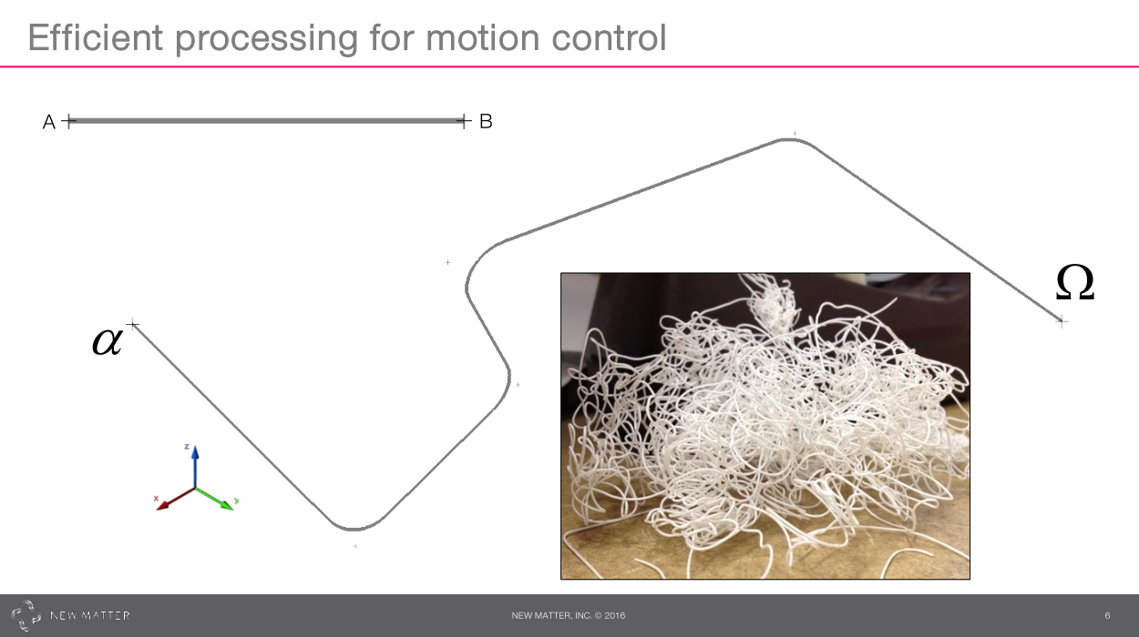
 You can make your own, one-off, 3D printer out of unobtainium, dragon scales, and the unbilled labor of a year’s worth of weekends. But if you want to make a product to sell to the general public at a reasonable price, it’s got to be built using commodity parts and work robustly. This is what drove [Derek] to use a DC motor with an encoder instead of the ubiquitous, heavy, and relatively expensive stepper motors that most other 3D printers use. Driving DC motors in open-loop feedback meant that none of the “standard” printer firmwares were going to work — he needed to roll his own. And that’s how we have this talk, about getting from A to C, around the corner in B, as quickly and accurately as possible.
Trapezoids, and the KISS Principle
There are a few ways to turn a piece of G-code that says “go north at 50 mm/sec and then go west at 50 mm/sec” into machine movement. One is to go north at full speed, slam to a stop, and then jerk off west at full speed. This is what the earliest versions of DIY 3D printer firmware did — and the result was noise, and vibration of the print head, and degradation in print quality. These were ugly times.
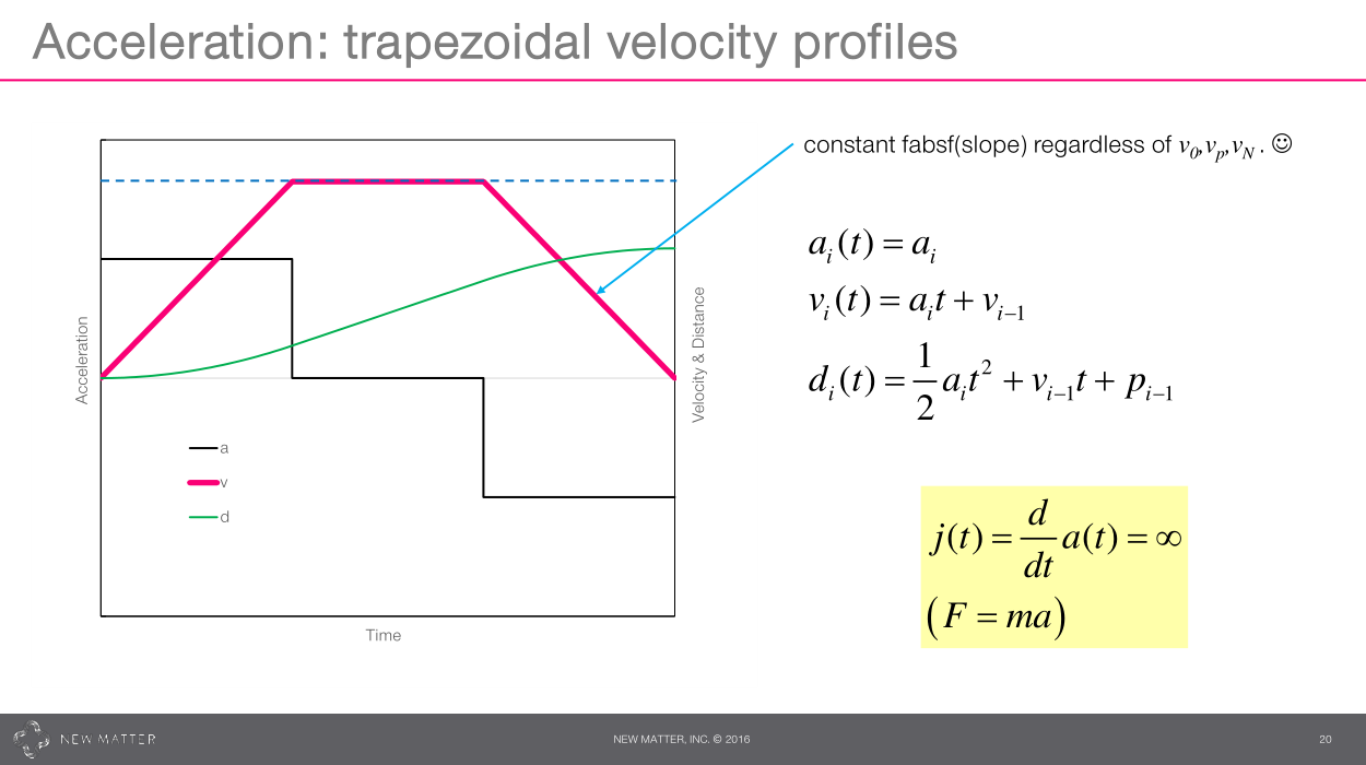 [Derek], and the path planner in grbl, chose the next most complicated solution — moving at constant acceleration for each segment of the path, resulting in trapezoidal velocity profiles. This turns out to work decently well in practice and be easy to compute. [Derek] added corner rounding to the routine: where the G-code said to make a sharp corner, the firmware would take a curved corner that’s close enough that it wouldn’t look bad, but also doesn’t require the nozzle to slow to a stop. Combining the two is basically the simplest solution that can work well.
Connecting a few segments together is the next step, but it lets the printer eventually come to a stop, whether at the end of the path or because a user pressed the pause button.
Closed-loop Control
Most stepper-driven 3D printers operate in open-loop control mode. The firmware tells the stepper motor driver to take ten steps forward and hopes for the best. When a printer loses steps, layers get de-aligned from each other, and if you’ve had this happen catastrophically in the middle of a print, you know why this can suck.
 [Derek]’s printer runs in closed-loop mode, meaning that if the printhead is too far south of where it should be, the firmware can tell that this is the case and apply more power to a motor to get it back right. Again, [Derek] chose one of the simplest methods that could work: PID control with feedforward. Of course, this means calibrating the algorithm to the machine, but a well tuned PID algorithm is a joy to watch.
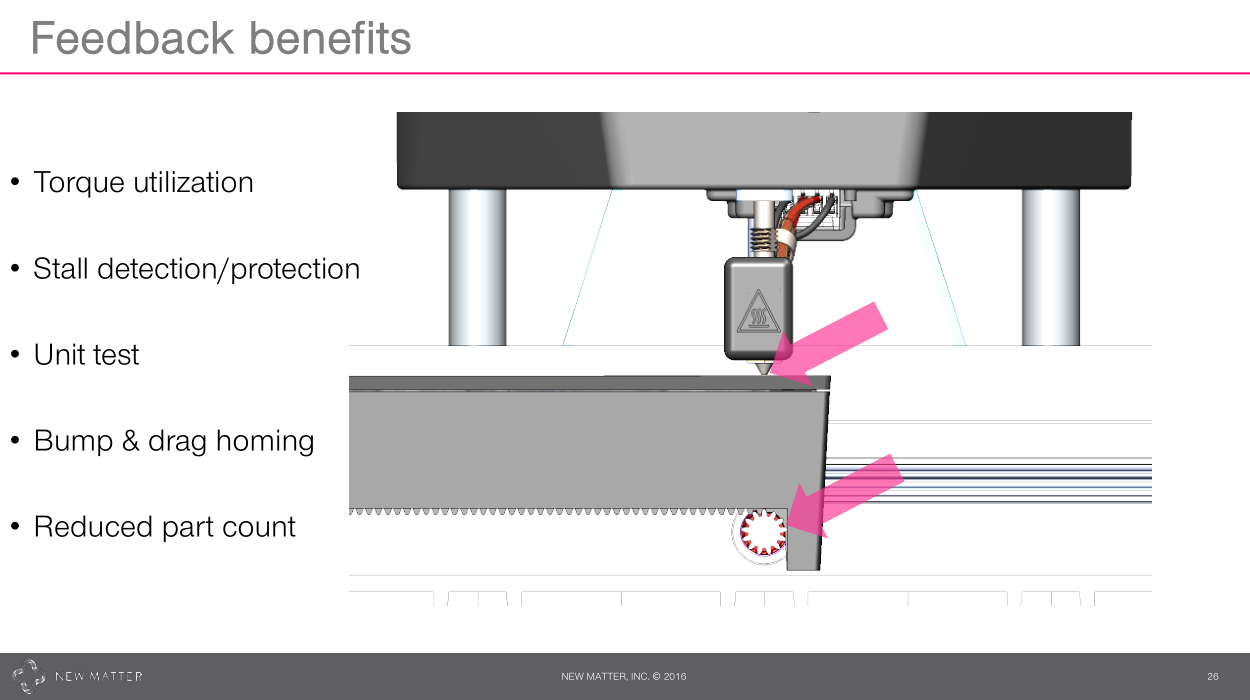
And the closed control loop provides additional benefits. Where stepper motors have to be way overspecified to avoid the dreaded missed steps, closed-loop DC motors can get by on lower torques. The coolest trick that [Derek] plays with the feedback, however, is in using the ability to detect motor stall to home the printer. There are no limit switches on the three physical axes. Instead, when the motor hits the end of its ability to move, the firmware detects the stall and uses this to zero the coordinate axes. This reduces parts and simplifies the device. We’re all for that.
Conclusion
 [Derek] designed his motion planning routines on the same tools that we all use, and used basically the simplest possible algorithms that would work well, avoiding “academic” complications for their own sake. In the end, this allowed him to optimize for speed, look fifteen steps ahead, include some necessary special tweaks like logic for dealing with very short segments and get the product out the door for a reasonable price. Motion planning and control in a closed-loop system is never simple, but “apply the KISS principle as far as possible and then tweak for performance later” is something that all of us hackers could stand to get tattooed on some suitably long part of our bodies. Better still, let’s just thank [Derek] for the reminder and exemplification!


I don’t know any 3d Printers that use a “glorified Arduino Uno”. Maybe you meant Arduino Mega?
Which is a glorified Arduino Uno. There you go.
Arduino Guno?
Arduglorino?
Jokes aside, closed loop feedback should be STANDARD on almost any 3d printer that relies on, well, MOVING ABOUT FOR HOURS ON END. Seriously. Any legitimate CNC platform needs to know where the head is, not tell it to move and hope for the best and then rinse and repeat thousands of times. Glad that somebody also values that enough to incorporate it into their products.
What people don’t understand is that any condition that causes a stepper motor to fail will also jam a servo motor. There is no magic in a servo motor that lets it overcome mechanical binding or collisions. The only advantage of a servo in that situation is that the printer will detect the failure and stop immediately.
I’ll be clear, any situation that causes a stepper motor to fail will also cause a servo (of similar peak capability) to fail.
The advantages of a servo motor are better efficiency (no need to burn power when doing nothing), improved accuracy (encoders to 10k+ counts/rev instead of 200 step motors), and tighter control loops. If anything servos are less reliable than steppers due to their complexity.
Failing immediately due to a disconnect between expectations and reality is critically important to begin with. That SHOULD be happening for any printer! That’s not the only advantage, that should be a basic requirement. But aside from that, there are other relevant items at play here though too. Things like backlash or drift or even mechanical wear that an open loop will never see. Especially when you multiple it out by the many hours or more of a typical point based extruder based 3D printer.
I agree that nothing is able to easily recover from something like a head strike or the entire head binding but those are much more fringe than small drifts on open loop systems. Particularly cheaper ones where precision isn’t quite as baked in to begin with.
Servos as used here wouldn’t solve wear and backlash, because those parts of the printer aren’t included in the servo loops. You’d need position feedback from the head rather than from the motor shafts.
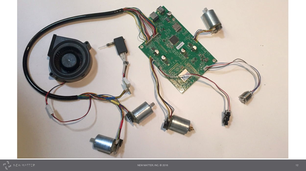
Ryan Turner; Um, no. Any drive can jam, of course. But a servo can keep track of its location, therefore it can recover its position once it gets through the jam. A stepper cannot. Lost steps are lost forever. This, my friend, is the difference between open loop and closed loop. Regarding complexity — the extra complexity you add with the encoders is made up in the simpler drive electronics. Look at Schulte’s board again, where are the heat sinks? Where are the MOSFETS? Might need a magnifying glass! If you’ve ever disassembled an inkjet printer you’ve seen similar: barely-there drive electronics, dc motors, and optical encoders. I built a large gantry CNC router using closed loop, and all 3 axes are driven by the 12v rail from a single ATX power supply. There’s no question in my mind which system is cheaper, simpler, and more reliable. http://www.dansworkshop.com/2016/04/large-gantry-cnc-router/
Open loop stepping drives combined with a properly written and calibrated firmware literally do billions of steps without loosing a single one. A pressure to get away from that barely exists.
It’s not like servo drives were invented just yesterday. They existed even before steppers. Still steppers took over on many applications, because they’re so reliable and easy to handle. Servos, for example, require to calibrate a PID loop for each motor. No such thing for steppers.
Um, which is exactly why every industrial sized CNC machine is running servos and not steppers, even though steppers with required torque do exist.
Steppers are great, but the problem is not about losing steps. That’s a red herring problem coming from poorly designed 3D printers where the steppers are sometimes being driven faster than the elecromechanical limits of the often under-dimensioned (and cheap) steppers allow.
Stepper in a well designed and maintained machine will never lose steps. The real problem is compensation for things like backlash or time-varying slop in various gears and rails (things do wear out over time) and error condition detection. None of which is possible to do with a stepper but it is absolutely essential on a machine that needs to produce repeatably good parts down to a few microns accuracy, every day, all year long. Closed feedback loop drive with encoders placed in strategic places (not only on an output shaft of a motor!) will give you that.
Wow Jan, somebody that actually knows a bit about what they are talking about on Hackaday. Correct , a correctly designed and mated motion/stepper system will never lose steps. Unfortunately we have the RepRap community to thank for all the nonsense surrounding steppers and their usage, and the myth that DC servos are somehow the answer to the woes. Yes, an encoder on the motor shaft only does very little to combat the issues. Absolute encoders on the moving platforms etc. , as are used in industrial machinery , are required.
I’m always thinking of ways to improve on my CNC machine, and having a closed loop with motion encoders one thing that I think about. It seems like there is an inherent safety of the open loop stepper system. I think of a worst case where my controller machine were to crash, or a sensor wire were to short or cut. Since the controller is sending coordinated direction and step pulses, it seems unlikely that any motor could randomly speed off in an uncontrolled fashion.
What would happen if there was something wrong with the position sensor in a closed loop. If the controller sees that the motor needs to be moved and sends power to the motor to get the correct position, but the position sensor does not respond so would the controller keep the motor powered? Perhaps driving the cutter through the table?
Sputnik77: I honestly don’t know about the whole industry, but the handful of CNC machines I’ve worked on all use incremental encoders for their closed loop systems. They work perfectly fine and they’re repeatable even between restarts. I won’t say absolutes don’t have their place, just that they aren’t required
Filter: well if the encoder goes faulty, a motor drive can go into “runaway”. It can be unsafe to be around if that happens. Which I suppose could be prevented just by having a watchdog, if it doesn’t see encoder pulses in a certain amount of time, throw a fault.
My Chinese Prusa i3 knockoff printer’s controller has an Atmega328p at its middle. I’d call that a glorified Arduino Uno.
You’re sure about that? GRBL is the only motion control that will fit on an UNO. The 328 doesn’t have enough IO to run a 3d printer.
Teacup Firmware easily fits on an ‘328, too. Quite a number of people run 3D printers with such a controller. There are even RAMPS-like boards for Arduino Nanos: http://www.reprap.org/wiki/SinapTec Obviously there are enough pins.
Oh, very interesting. Learn something new every day.
No idea. All I know for sure is the chip says 328p, the USB drive came with an old version of the Arduino installer, Windows recognizes it as a COM port, but none of the software I’ve tried recognizes it as a 3D printer.
I plan on building a more robust control board anyway, so I’m not worried about it. For now I’m happy to print off an SD card.
Also there is http://reprap.org/wiki/NanoHeart
More info about this solution and new version is on http://halfakop.ru/doku.php/reprap/electronics/nanoheart_v2
It’s not like CNC systems based on servomotors (collectively, the motor, the encoder, motor drive electronics, PID controller etc) are something new and novel.
Somehow “Fuzzy Logic” comes to mind.
As a very very non-English speaker, I feel empowered to say that this article is well written: I can read it and easily understand it, and I even recognize a style that is both clear, relevant, and not without humor…
Any chance this firmware will be open-source? I would love to see the nuts and bolts of the servo control.
+1, I would too
People have been doing this for a while already using a path-planning firmware like GRBL or Smoothieware, and one of the current Open-Hardware closed-loop solutions like Mechaduino ( https://www.kickstarter.com/projects/tropicallabs/mechaduino-powerful-open-source-industrial-servo-m ) and friends.
It’s all still based on the same standard step/dir interface used in open-loop solutions so it’s a very painless switch from one to the other, and no need to re-invent the wheel either with a new firmware.
Agreed Arthur , and it didnt even begin there. Nothing new or special here.
All very well, but where the devil did he find a decent encoder at anything approaching a reasonable cost? Every time I’ve looked, either they’re crappy things intended for user interface knobs, or they cost hundreds of dollars.
You are looking at the wrong products. Optical kit encoders are frequently added to motors and are <$25 even in retail quantities: http://www.usdigital.com/products/encoders/incremental/rotary/kit/E4T
Low-end magnetic encoders can be even cheaper, you attach a small magnet to the motor shaft and an IC that will detect its angle with 12-16 bit resolution is <$3 in quantity.
well, you have to know where to look:
https://www.pololu.com/category/201/encoders
It’s really an entirely different cost situation when you are using high volume suppliers. We worked with our supply chain to find a very cost-effective solution (far less than $25/motor), in fact, substantially cheaper than any NEMA17-sized stepper (in volume).
Uhm, NEMA17 steppers are somewhere between $10 and $15.
Uhm , no, they are much cheaper than that.
Yeah, but they’re big and heavy. All that weight willl add a lot to the cost of shipping.
For a good NEMA 17 it’ll more expensive than that. Also, DC motors would make it a hell of a lot lighter. All that weight will add a lot to the cost of shipping.
Indeed, in bulk, ~$5
These ones include the optical encoder and seem affordable and powerful enough for a regular size 3D printer at less that $10 each (and not buying bulk) https://www.aliexpress.com/item/MITSUMI-545-permanent-magnet-DC-motor-grating-speed-4470-to-6V-24V-1120-motor-DIY/32751990902.html
For me, I disassemble old 2D inkjets. I got them for free using various sites. You can usually find 2 per printer – 1 in print head (linear) and 1 in paper movement gear (rotary).
If you want to play, look in your trash bin. The encoder wheel in one of the photos along with the fork-type sensor are what you will find in a typical cheap inkjet printer that is thrown away after it inevitably breaks. They are typically used for the paper feeding mechanism. The second type are the linear tape-type sensors, with the marks being on a tape instead. Also abundant in every inkjet – used to drive the head on its rail.
“Driving DC motors in open-loop feedback” -> closed-loop
“chose the next most complicated solution” -> least complicated
Too bad the design is mechanically unstable by itself… Open Source would be way better! 399 is also still expensive for a machine with such a tiny build envelope. This is basically a glorified printrbot with servos. So what’s the real benefit again? Saving a few cents on switches? If the motor stalls, the force it delivers is too weak. The position sensing isn’t going to help there.
That’s right, if the motor can’t blast an axis right out the side of the machine in a cloud of shrapnel, the force it delivers is too weak. [/sarcasm]
It’s a pretty useless upgrade, the sensor is on the motor.
This does not solve the problem that the current GCODE slicers output is already bad. There are disconnected paths everywhere. The print head goes to one place and prints, then stops printing and goes to another place. And all of that on a single layer. It would be quicker and produce better prints if the slicer would combine adjacent paths. I have seen no option for this yet in slic3r and cura though, and looking for a GCODE path optimizer leads you to obscure, non-compiling projects…
Sounds like you need to use ‘seam: nearest’ in slic3r.
Nice! Didn’t know about that option. Thanks for the info!
Because the difference between the “quick and dirty” and “brute force” algorithms for path optimizations is about 2% travel distance on most models. So optimizing these few “odd” jumps doesn’t provide a lot of improvement at all. While it does cost a whole lot more computation time. (Traveling saleman problem)
FYI, I made the CuraEngine.
Won’t the 2% of travel distance considerably add up on the final time of the print?
Nowadays computing power is cheap and plentiful, offices are literally scrapping Intel i3 and i5 CPU machines, the computing power of these is pretty significant (compared to something like a RasPi)… how much more computation (…time?) are we looking to get those 2% of less travel?
Then thanks for making Cura, it is a good slicer, indeed!
I have seen models where slic3r faired very bad. From my amateur perspective it looked like it could be improved a lot. Afair it was mostly the inner/outer shells that were totally disconnected.
If it is about computation time vs. print time, why not add an option / slider how much time the engine will spend on the layer till moving on?
I’ve been considering a feedback setup for my own CNC
I think the best setup is probably machinekit on the beaglebone, perhaps with a Cramps board which can use it’s PRU’s to handle the real time motion control and feedback at the same time
https://groups.google.com/forum/#!topic/machinekit/H5vfY5KJkKE
https://www.youtube.com/watch?v=XVpX7CBQRh0
On a tangent from the “infinitely sharp corner” point from the article: instead of completely coming to a stop for a corner, could you make the bed move as well as having the print head move? I realize this would be complicating the build and making it more expensive, but a moving xy bed in addition to moving print head, both running the trapezoidal velocity profiles, could make a “good enough” corner a lot better. If it worked right, the interaction between the moving print head, and a moving xy bed would be a print that “stopped at the corners” when both were actually in motion.
I’m speaking as a total CNC/3dprinter newbie, so I’ll be putting on my flame resistant clothes now.
That would only make slope of this trapezoid a little more steep. You can achieve this just by using bigger motors and it will be less complicated (no need for separate drive).
“On a tangent from the “infinitely sharp corner” point from the article:”
I see what you did there.
In the words of Rodney King, cant we all just get along??
I have designed (and built and sold) FPGA based robots with servo motor and encoder feedback. Yes they kick ass. Yes they are expensive as crap. Yes this “method” would mean THOUSANDS of us hacker having to throw away our RAMPS and stepper motors and cause us to buy expensive servos and encoders and FPGA’s (or at least ARM cpu’s with decent timer counters) .. AHHHH but there seems so be a better way…..
What if we all attached cheap (shitty) little magnets to our lead / ball/ belt screws / pulleys and used a AS5048 i2c magnetic encoder from ams to read-back the position of the stepper motors we all own and know an love?? the beauty there is that the stupid magnetic encoder chips do NOT require a heavy real-time CPU burden to read (like optical encoders do).. and the do not require expensive-ass touchy alignment sensitive optical encoder either!!! The software could casually check the AS5048 at the END of each G-code move, and evaluate if it “felt like” a stepper shit itself and missed a bunch of steps in the last move, and then make a decision to either catch-up or wail and moan to the printer operator..
The point is that there are now wonderful alternatives to optical encoders (and the complexity of dc motors with feedback) right before our eyes.. Someone here has even already done this to a limited extent (a few moths back in HAD some genius already married a magnetic encoder to a stepper, but did not provide a complete 3d printer solution ) So, you stepper jihadists, simply marry the magnetic encoder to the RAMPS firmware of your choice, and lets further disrupt the 3d printer market!! Shit.. add this idea to a smoothie board and you end up with a super-smoothie ?? perhaps a “frosty”?? a “frosty” board???
For what it’s worth, I noticed that the motion control of a line of high-end pan/tilt/zoom security cameras was done years ago with direct drive via inexpensive stepper motors and 20 bit resolution Agilent optical encoders. The Analog Devices Blackfin DSP controlling them was programmed to use similar acceleration profiles for maximum agility and precision. It also avoided and compensated for all mechanical resonances and even the slight nonlinear characteristics of microstepping the motors. It also dynamically varied the stepper motor drive voltage depending on the load on the motor, keeping power and heat to a minimum. Some truly remarkable code from a combination of C, assembly and Matlab.
So you can have your cake and Edith, er, eat it, too!
I don’t care what it is.. If it produces better quality or better economy it’s well justified even if by a very small margin..
3D Printing is moving too slow.. We need to get it accessible and cheaper quicker.. It’s still too much like CNC. A usable printer is like $400.00 and a good delta is $1,000.00. The documentation is always bad and software is just now getting end-user friendly..