
If you’re reading these pages, odds are good that you’ve worked with I²C devices before. You might even be the proud owner of a couple dozen sensors pre-loaded on breakout boards, ready for breadboarding with their pins exposed. With vendors like Sparkfun and Adafruit popping I²C devices onto cute breakout boards, it’s tempting to finish off a project with the same hookup wires we started it with.
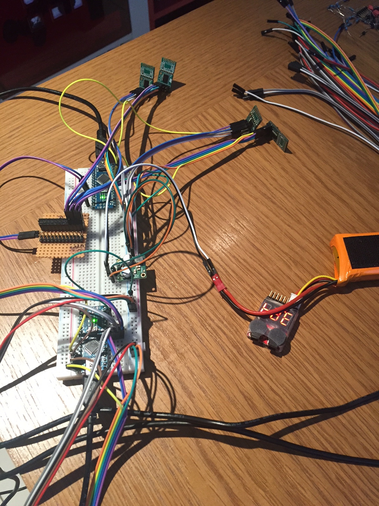
It’s also easy to start thinking we could even make those wires longer — long enough to wire down my forearm, my robot chassis, or some other container for remote sensing. (Guilty!) In fact, with all the build logs publishing marvelous sensor “Christmas-trees” sprawling out of a breadboard, it’s easy to forget that I²C signals were never meant to run down any length of cable to begin with!
As I learned quickly at my first job, for industry-grade (and pretty much any other rugged) projects out there, running unprotected SPI or I²C signals down any form of lengthy cable introduces the chance for all sorts of glitches along the way.
I thought I’d take this week to break down that misconception of running I²C over cables, and then give a couple examples on “how to do it right.”
Heads-up: if you’re just diving into I²C, let our very own [Elliot] take you on a crash course.
Bugs–What Bugs?
Ok, so maybe I routed a couple feet of cable carrying I²C through my robot chassis to talk to my sensors. What’s the big deal? Once we start running signals over cables, there’s a host of assumptions that start to break down. Let’s take a quick tour of the two biggest challenges that are all too eager to bite us: bus capacitance and EMI.
Stretching out our Bus Capacitance
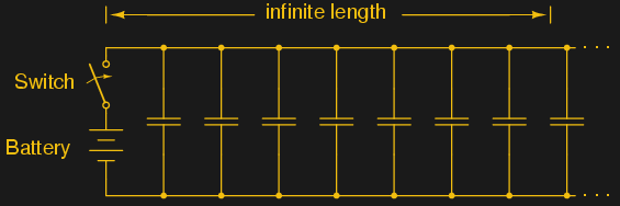
First, there’s the capacitance of those long wires. Remember, capacitors are just “two conductors, separated by an insulator.” Sound suspicious? If we look at our cable topology, a signal wire and a ground wire form exactly that–an unwanted capacitor! The longer our cable grows, the bigger this capacitor grows.
OK, so now that we know there’s a capacitor in our system, what, exactly, is it doing to our signal? In the ideal world, or at least when our conductors were short, we could expect a pretty short delay between the time our signal takes to exit one device and enter the next. In fact, it’s so short we can pretty much forget about our bus capacitance altogether. However, as that wire distance grows in size, that parasitic cap takes our nice clean signal and starts attenuating it.
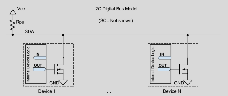
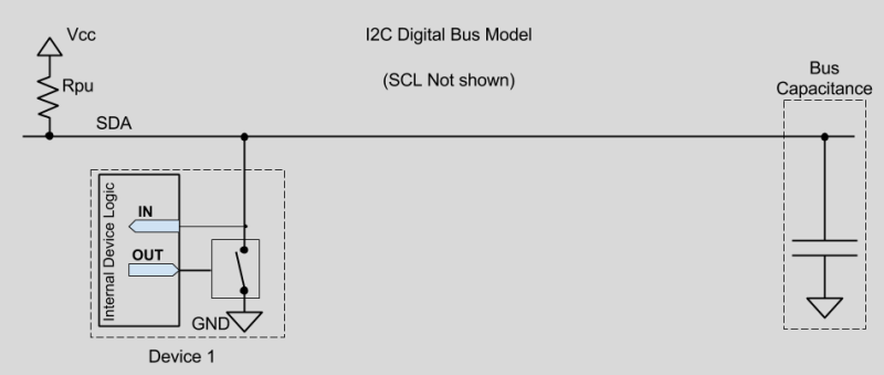
Why is this happening? Let’s look at the bus architecture. I²C implements open drain configuration, which means each device has a MOSFET on it’s input, enabling it to pull the entire bus down to “logic 0.”
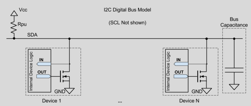
Assuming we’re running our I²C bus over a long cable, let’s now add our parasitic bus capacitor into our diagram.
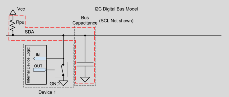
With a little re-jiggering, let’s just examine one device and now model its transistor as a switch.
Behold! A wild lowpass filter has appeared!
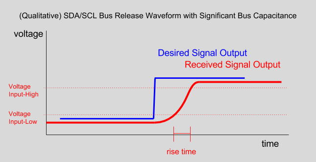
When any device releases our SDA or SCL line from low to high, modeled above as a switch opening, we can’t just change the value of the bus instantaneously. Why? We must first pass our signal through this low pass filter, or, in more conventional terms, charge up this parasitic capacitor. The result? The received signal emerges not in that pristine, staccato square wave that we all know and love, but a diluted representation of the original, as if staggering back home from a rough night at the pub.
Fun Fact: Bus capacitance primarily affects rise time, not fall time, since the N-channel MOSFET which closes to create a “logic 0” signal is essentially creating a short to ground, bypassing the capacitor altogether.
With a stretched signal running over long wires, we need to start worrying about keeping that rise time sufficiently low for our receiving device(s) to read incoming signals correctly. Rise time is the amount of time for the voltage to reach a valid “logic 1” threshold level before it’s read. For I²C, the spec dictates 1000 nanoseconds for standard mode (100 kHz) and 300 nanoseconds for fast mode (400 kHz). If we stretch our rise time any farther, we’ll risk sending over bits that don’t get recognized as either a “logic 0” or a “logic 1.”
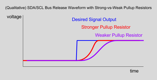
Fortunately for us, we have a slight amount of control over this rise time; we control it by changing the value of our pullup resistors. First things first, though: let’s clarify how pullup values influence the I²C bus. Earlier, I mentioned the stray capacitance coming from those looong wires running from master to slave device.
A stronger (fewer Ohms) pullup resistor decreases the rise time of our signals by increasing the allowed current that can flow through either signal line, which, in turn, charges our parasitic capacitor faster.
OK, so just how far can we go? Just how small of a resistor can we spec? If we want a snappy rise time, why not just go with a 100 ohm resistor–or something smaller? Unfortunately, with a stronger pullup, the amount of current that any one of our bus devices needs to sink will also increase. Let’s have a look at that diagram again.
Notice how N-channel MOSFETs are baked into each device? These FETs are responsible for actually driving the bus low, which, in turn, changes the bus values to either “logic 1” or “logic 0.” Since those MOSFETs are internal to each device, they’re limited by just how much current they can sink through the corresponding device without damaging it. Fortunately, the I²C spec actually dictates the maximum sink current; it’s a puny three milliamps. Hence, with only 3 mA, the strongest value pullup resistor gets very quickly limited to the low kiloohm range at best.
If you actually have an application where you’re operating somewhere in the range of these limits, you’re in luck! TI has put together the necessary equations to calculate bus pullup resistor values in one application note. Nevertheless, keep one thing in mind: the range where we can play this trick of reducing bus capacitance with stronger pullups only goes so far. Most people don’t care–and rightfully so, since most people don’t run I²C down a long cable in the first place to such an extent where bus capacitance actually matters.
Our problems with running I²C down a long cable don’t stop with bus capacitance. There’s one more foe that’s arguably far more nefarious.
Mischievous Bit-Flipping
We can thank the smartphone industry for gifting us with some pretty killer MEMs sensors, most of which speak I²C. With sensors like ST’s VL6180 time-of-flight sensor (Sparkfun Breakout) and Bosch’s BNO055 IMU, it’s tempting to cram these sensors into the corners of our robot chassis over long wires. Hold up, though. Robot platforms smell of moving parts, and moving parts smell like motors–which are huge sources of electromagnetic interference!
So, what exactly does EMI do to harm our system? EMI can induce voltage spikes on long cables. Remember: every long wire is, at heart, a good ol’ antenna, susceptible to picking up nearby electromagnetic waves. In a classic analog AM radio, changes in the amplitude picked up by this antenna would convert to audible sound. A digital system, however, doesn’t interpret continuous waveform amplitudes. It only interprets two threshold amplitudes which translate to a binary 0 or 1. While EMI might take on an analog form, we start to see problems when those unwanted EMI-induced voltage spikes cross those thresholds of the digital domain. The consequences? For our I²C bus, these induced voltages can translate to unwanted bit-flipping. Fancier protocols have error-correcting codes designed to handle occasional bit flipping and request a retransmission. Alas, I²C has no such thing.
Solutions for Long Runs
Bus capacitance and EMI are the two most common issues when we decide it’s time to run our I²C and SPI devices over long distances. Luckily, there’s a chorus of off-the-shelf solutions that are ready to handle these scenarios. Let’s take a tour of what’s on-hand.
Shielded Cable
For short cable runs, the easiest way to mitigate the noise risk would be to simply run the native SDA and SCL signals over a shielded cable. By far, this solution requires the least effort because, cablewise, it’s merely a facelift. Note that this solution only mitigates noise, and does nothing to solve the issue of bus capacitance. For that, you’ll still need to spec an appropriate pull-up resistor.
Using shielded cable properly means we’ll need to ground the shield at one end. A shielded cable with the shield left ungrounded is merely dressed for the occasion, but it’s completely useless. A shielded cable with the shield grounded at both ends is now a ground loop (aka: antenna), which is almost as bad as leaving the cable unshielded to begin with. The rule from here-on-out: ground the shield at one end and one end only.
To make life easy for us, manufacturers usually add a naked extra wire, called the drain wire (seen on the left), which is electrically connected to the shield. Simply ground this wire at one end, and we’re done!
Bus Buffers
For long cable runs, some dedicated ICs can buffer the I²C signal, enabling the signals to run down a pair of wires with a much higher capacitance than what’s typically allowed on the I²C bus. The PCA9605 enables devices to run at the maximum allowable bus capacitance (400 pF) of the I²C spec. The PCA9605 takes that limit even further, allowing up to 4000 pF on the cable side.
The P82B96 does that, and a bit more. In addition to allowing a higher bus capacitance, it also enables the bus to run at a boosted voltage, making it even more noise immune. What’s more, the P82B96 can even be optoisolated, enabling interaction between devices on dissimilar power supplies. The datasheet boasts carrying an I²C signal across cables for up to 20-meter cables. Furthermore, by dropping additional P82B96 devices downstream along the cable, the signal can be boosted and regenerated to travel even farther.
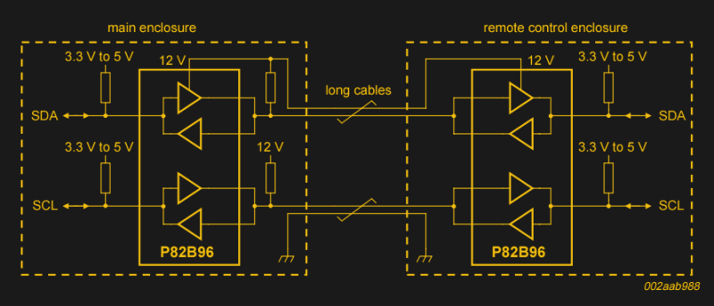
Keep in mind that systems with P82B96 chips will come in pairs, as shown above. This pairing is necessary to take the boosted I²C signal from one chip and re-encode as conventional I²C with a bus voltage that’s sane enough for our remaining I²C devices.
Differential Bus Buffers
While some bus buffers simply boost the voltages of the I²C bus, others re-encode it as a differential signal. The PCA9615 does just that. It encodes the SDA and SCL lines into two split differential pairs. Differential pairs are one step short of magic. By sending equal-and-opposite signals over two wires spaced closely together, we make the signal far more noise immune than simply by boosting the voltage. (More on differential signals and the PCA9615 in an upcoming post!)
Of all the solutions so far, this one’s my personal fave. Not only do we get all of the noise immunity benefits of differential signals, we also don’t sacrifice the main benefit of I²C: that it is a shared bus and, hence, only a small number of wires. On that note, this chip also supports a multidrop configuration, making it a true off-board extension of the protocol.
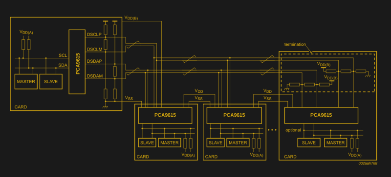
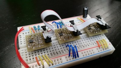
In the diagram above, the large bounding boxes reflect multiple PCBs–each of which is connected at arbitrary points along the same cable. By far, my best bet at taking this diagram and turning it into real components was to start with ribbon cable and simply crimp connectors along the cable like so. (Those cable lengths, however, can span a few meters without any problems.)
With typical bus buffers, sending a boosted signal across a ribbon cable would still introduce the possibility of EMI in the noisiest environments. With a differential signal, that’s no issue, provided that each pair is closely spaced together on the cable.
As opposed to the prior solutions, each node that connects to this setup has the same topology, just one PCA9615 per drop. There’s one exception, though. The final drop needs to have termination resistors that complete the differential pair topology.
Years ago, running high speed signals over long wires may have been a huge headache. Nowadays, there are boatloads of ICs ready to give us a jump start in this realm. Those drop-in solutions may have have been the toils of our predecessors, so I cited the main application notes at the bottom of this article. Nowadays, in my mind, running I²C over long cables is a solved problem. If we follow the recommended guidelines, we’ll be well on our way to implementing an out-of-the-box solution that “just works.”
Join us in the coming weeks as we look into specific implementations that tackle these problems in gritty detail. Until then, cheers!


Don’t use I2C for long distances. Use something like RS485 instead.
I was told in college that RS-485 was dead and not worth learning about (as well as RS-232, 422, LVDS, GPIB, SCSI, IDE, Parallel, several other interfaces, and discrete logic circuits) and was amazed when I started my first industry job and started having to interface MSP-430 and ARM MCUs with all of them.
I’m seriously considering running RS-485 through the unused pairs in my 10base-T LAN for home automation.
I have RS-232 running over unshielded Cat5e in my home. Probably a 60 foot run. Zero problems at 115200. RS-232 is extremely forgiving, much more so than I2C.
RS-485 is alive and well. In addition to a lot of industrial uses, it’s the physical layer for the CAN bus used by all modern cars.
wtf? No. It is nothing of the sort.
CAN and RS-485 have *nothing* to do with each other.
Mwa, “nothing” is a strong expression in this context.
The physical layer of CAN is somewhat similar to RS485 in that they both use differential signalling. The difference is that RS485 drives both lines in push pull fashion (or both idle if inactive) while CAN only sinks to ground and uses external pullups, somewhat similar to I2C.
The biggest practical difference is that CAN has a dominant level, which is used for early collision detection, whereas RS-485 doesn’t.
CAN means not only a different physical layer, but a whole transmission protocol.
The CAN-Peripheral in a µC takes care of the message Transmission, beginning with arbitration, Acknowledging, crc-checking, error handling, message filtering and re-sending in case of arbitration lost or no acknowledge or error.
With RS485 you will have to do this all in Software.
Nevertheless with RS485 you are not bound to the maximum of 8 Byte Payload per Frame.
They ARE both industrial high-noise environment buses.
You’re thinking of DMX512, for theater/stage lighting. That protocol is still alive and well and uses EIA-485.
I didn’t know that, I’m just becoming familiar with DMX..
Whoever told you that was highly uneducated. RS485 is alive and well in industrial and commercial worlds.
+1. We use RS485 for very serious industrial automation. We use it in news systems. In some places, we are replacing canbus with RS485 (where canbus is overkill).
Uneducated? No. He had multiple engineering PhDs and was an excellent professor.
Out of touch with current industry? Definitely.
Epaulettes. That’s all I’ll say. Just because someone jumped through some hoops and got the equivalent of military rank and costume, doesn’t mean they’re an expert on what they’re teaching you.
If you EVER find yourself saying “I was told in college that ‘xyz’ because ‘so and so’ professor told me so”, just STOP. Stop and do some actual research or get a second opinion. Objective reality doesn’t start and stop with a single person’s opinion. Unless you’ve actually gotten a consensus from at least a few experts, or actually researched it yourself, then consider it nothing more than unverified claims. Skeptic’s creed. Show me the evidence. Everything else is just opinion.
A lot of those old comms protocols are more like sharks than dinosaurs. They may not be the newest thing, but they’re a lot tougher and more noise resistant than newer and more “high tech” options like USB. They’re protocols that have hung around and not changed because they don’t need to change; the original design can still compete in the environment it was designed for.
I like your analogy.
If you’re running Gigabit ethernet, you have no unused pairs. Gig-E uses all 4 pairs of the CAT5/6 cable for data transmission.
See here for more info: http://www.hardwaresecrets.com/how-gigabit-ethernet-works/
We use RS485 in most of our applications due to the cost, distance and relatively low bandwidth requirements. RS485/RS232 are still very common in a lot of industrial modules.
If only CAN enabled hardware was not so expensive.
This is just like mixing VoIP and Data devices in the same network, This is a really bad idea. Ethernet cable is really cheap. Please see my blog: https://www.element14.com/community/people/phoenixcomm/blog/2018/06/06/nexgen-sim-converting-the-game-port-to-usb-atr-boxes-and-real-life-part-4 or http://www.smarthab.us
Given the very low cost to make a whatever to TCP/IP gateway these days you have to wonder if sending anything else over long wires/air/fibre makes much sense. It will come down to the exact application and the scale of what you are trying to do, the number of sensors etc. With an ESP8266 pulling down NTP data you can hook it to anything and then stream very accurately time stamped sensor samples to whatever back-end you like, you can even multicast the data. The ESP on networking over wires is an option if WiFi isn’t, http://hackaday.com/2016/07/01/wired-networking-for-the-esp8266/
Overhead and needlessly complicated comes to mind.
Or just K.I.S.S.
how well does ethernet work when run directly parallel to 660V @20A (full of motor noise/spikes/rf) ??? oh, you need to drill a new hole in the wall thats farther away from the power? the old system worked fine as-is, anything newer should be better, right? I dont get it; theres two seperate conduit holes… should be okay? why are you trying to bill me for a huge construction project and retrofit of ALL our stuff, when we just want our new robot installed andor upgraded. oh right, you think we need 10/100 megabit? the machines only need to transfer 32 bytes per second… WHEN there is a need.
yes, you are right, the ethernet should not be run that way… but it is, does not work. you get fired/laid-off because you say it cant be done eventhough you removed the one where it DID work, then your replacement re-installs the old one, with an off-the-shelf converter, (after spending days learning outdated stuff, i know, so painfull) ironically, doing the REVERSE of what you reccomend; I2C/SPI/ect to connect a “modern” robot to your existing “working” systems without having to revamp all machines, cabling, holes in walls (proximity to high power EMI) routing, and central control.
also wifi is not acceptable for secure communications. for example; phosphene gas pressure vent controlled by wifi? i would not even approach the building unless it was to decomission the wifi. that way intruders have to get by the guards and cameras and locks and nothing bad happens. no insurance would cover you if they found out your phosphene gas was “secured” using wifi, and that it “accidentally” got bridged (between the isolated wifi and the world-wide-web) after an employee accidentally got a personal laptop/tablet/smartphone infected with a phishing scam and forgot to turn off laptop when driving to work… but how did they know? you logged into your work email and the scammers now know everything and sell it to much worse scammers that sell it to the very-very bad people.
leave the wifi for the cameras and web, that way if anything happens, we keep making money. if we put criminals out of buisness, they will turn into web-trolls and wont be able to bother us at work or while sleeping (safety of factory nearby).
PS: the existing systems already have time-stamp ability and run on a number of sometimes interchangeable comms systems.
I got fired from a commercial writing job for writing about what a very bad idea the “Smart Grid” is. They had advertising to sell. I had grid integrity to think about. Not to mention my reputation. Ah. Well.
TCP/IP requires big connectors, faster, bigger, and more expensive processors, more memory, higher frequency, more power, and much more hassle in configuration. RS-485 just requires a UART, and a small driver chip.
I would leave out the connectors in this. TCP/IP -> RJ45 (small), RS485 normally SubD9 (bigger). Of course RS485 would work over RJ45 too – or some expensive heavy duty waterproof military round connector.
Bigger Processor, memory, etc. of course true.
Yes and No, the connector itself is kind of irrelevant. I have seen ethernet broken out to small connectors and 485 using RJ45.
As for bigger processor, more memory, meh. Digi makes what is basically a longer RJ45 connector that is a ethernet to serial adapter with a built in web server. Not cheap, but perfect for when you just want to add ethernet capability to something.
OOps, XPort, not Digi
The problem is that getting an 8-bit or 16-bit MCU onto Ethernet either requires a lot of heavy programming (leaving little CPU time for actual application code), a more expensive MCU with an integrated Ethernet PHY (I’m using the Tiva-C ARM currently, 90% of the code is the TCP/IP stack), or a module that costs more than the actual MCU ($1 AVR plus a $10 Wiznet or ESP).
Nothing a little money cant fix: https://www.lantronix.com/products/xport/
True, and don’t forget to have proper protection and isolation against what can be wrong on the other end of the cable.
agreed.
i filled my bedroom with smoke by connecting some random low-voltage to the BNC terminal of a THINnet network card, needless to say, it was not up to industrial standards as it was intended for home and office and was labeled as such.
in industry, you have higher voltages (24V) and higher current (1-5A) then in my expierement. i maintain it was an expierement.
About 25 years ago I developed I2C –> RS422 and RS422 –> I2C bus adapters specifically for extending out I2C.
Worked very well :-)
I2C will function long distances 10 feet or so with the buffer drivers. Try to implement a design that requires Automotive EMI, 100V/m, with 32V short to supply short to ground, 15KV ESD, reverse battery etc. Do that and you are the I2C MAN! BTW that is stupid when there are CAN Chips, or wireless communication like the TPMS. Leave it to management to pick the project and run.
If you have a sensor that has an i2c interface, sometimes you have no choice, and adding a processor to change the signaling is not cost effective. If shielding and buffering does not work, the differential signaling PCA9615 usually works.
Great article!
I have one question. You talk about “long wires” without giving any specific length (AFAICS). At which point do we have to worry about cable length for I2C?
Thanks,
That depends a lot on the routing and noise sources. In a noisy environment, a few inches can already be causing problems. With the PCA9615 you get the best immunity, and the datasheet mentions up to 3 meter (10 ft) cable length for high speed.
Anything that leaves an enclosure is long enough you need to start looking at this.
I’ve used PCA9615 over 3m+ runs in a car and they worked great. I don’t have any data to show unfortunately.
http://www.i2cchip.com/constant_current_pullup.html
You can also use a constant current pullup that works better than simple resistors.
That suggestion makes a lot of sense but normally wouldn’t be the first thing I would think of.
Thanks!
“Resistor to a higher voltage and a clamping diode”.
I was going to suggest just that very circuit – but a constant current is faster.
Is that Hitler?
My thought exactly!
H. only had one egg. This image clearly shows two.
I thought Eva Braun had the eggs…
Same thing hit me! I was wondering why Hitler was abseiling on an I2C bus.
For some nice scope shots of the effect of varying pull-up values.
http://dsscircuits.com/articles/effects-of-varying-i2c-pull-up-resistors
Thank you for that awesome write up! I begin to understand why my blinkM clones wouldn’t run on multiple 30+ cm cables and several other things I’m embarrassed to tell :D
It would also be good to look at using an active pull-up on the far end of the wire.
LTC4311 – Low Voltage I2C/SMBus Accelerator is one possibility.
The ground loop advice needs to be taken with a grain of salt. The issue is more complicated in regard to digital.
http://www.sigcon.com/Pubs/news/2_2.htm
“In high-speed digital applications, a low impedance connection between the shield and the equipment chassis *at both ends* is required in order for the shield to do its job.”
But (and this is where the advice in the article is correct):
“In low-speed applications involving high-impedance circuitry, where most of the near-field energy surrounding the conductors is in the electric field mode (as opposed to the magnetic field mode), shields need only be grounded at one end.”
The type of ground loops you avoid by only connecting it at one end are generally from two pieces of equipment that are earth grounded or share a common ground through some other path. If you have a device that is being powered by a long cable that also supplies I2C, then you don’t have a problem. Connect the shield wire to the chassis of both devices.
Yup, I deal with high frequency impulses from a 3.4KV transistor switch all the time. The best rule I’ve found for signals is to ground everything. Afik, the “ground at one end” guide line comes from situations with large AC magnetic fields, or where the ‘ground’ at each end of the cable is a significantly different voltage. (in both cases, the ground loop leads to ground currents and voltage offsets in the signal wires)
At very high frequencies the ground can be superfluous because you most probably have a capacitive input anyway.
The real issue with ground is determined by the signalling type. Unbalanced, differential or current signalling is isolated from ground anyway but it may be required as a reference for Vcc of the chips at either end (not always the case) or connected to shield at one end.
Shield and ground are not the same and shield is normally only connected to ground at one end. Some coaxial cables have two braids and one signal the centre is signal, the inner braid is ground connected at both ends and the outer braid is shield – normally connected to some form of ground at one end.
In a balanced or ground referenced signal the ground has to be connected at both ends because it *is* the reference. This can produce problems to be solved due to *other* things that are *also* connected to ground.
RS-485 is true differential signalling and you don’t need a ground conductor. High speed differential signalling is typically not true differential signalling and requires a return conductor. The launch times even on high quality drivers are far enough off that it’s more like two single ended signals as far as the rising and falling edges are concerned. Additionally, with high sped signals, when the signal is on the PCB you aren’t going to get enough capacitive coupling between the two traces to get the inductance anywhere near what it needs to be, they need to be referenced to a ground plane. And thus you’ll also need ground reference as part of your cable.
And again, as far as connecting the shield, just like with all grounding schemes, the answer is always “it depends”. For anyone doing low speed signalling, especially audio (basically DC), the answer is almost always to only ground it at one end. Once you move on to high speed signalling, you usually need to ground it at both ends for it to be effective.
Just to make the designers job harder, you don’t need to electrically connect ground to have a ground loop anyway, at least ground loops not related to mains. Signals are perfectly happy to capacitively (or inductively) couple to whatever signals you give them. That capacitance can come from either the case, or from capacitors intentionally placed.
The P82B96 has an idle voltage of approx 0.8 volts on the device side whichnis a little too high for a lot of micros to interpret as idle. The PCa9600 is a much better choice in my opinion as it can idle at about 0.6V.
Taking I2C off a PCB is just stupid. Do it properly with RS485, or at least something that doesn’t rely on resistive pullups, or it will come back & bite you.
RS485 is too bulky to use in a robot.
Digital signals have their advantages.
You saying RS-485 is somehow analogue? It’s two wires… versus I²C’s three (with 0V reference).
I’m not sure what you mean by bulky, if your device doesn’t support it you can use a max485 chip which comes in many tiny packages.
Pssst, don’t tell the automotive industry they’re doing it wrong with their millions of LIN bus nodes.
LIN is only 19k2, and the pull-up is 1K, so that makes it less of a problem. It’s also a 1-wire bus, so you don’t have problems with crosstalk. It’s single master, so you don’t have problems with bus collisions. Looks much more robust than I2C.
And it uses battery voltage (whatever that is at that moment) as signal voltage. Except for the higher level protocol I would compare it much more to RS232 than I2C. It also uses a UART.
This was a joy to read, and quite insightful.
Keen to see the rest.
“A shielded cable with the shield grounded at both ends is now a ground loop (aka: antenna), which is almost as bad as leaving the cable unshielded to begin with. ”
Ehhh???? This is wrong/bad practise.
A ground ‘loop’ must actually be a ‘loop’ in that there must be two distinctly different path from one point to another.
Your example is true, where for example, you have audio equipment and the chassis ground from the power outlet is connected to the ground on two different piece of equipment and then adding a shielded cable where the shield is connected to ground at both ends. This creates the two paths of the ‘loop’ one part being the audio cable shield and the other being the ground wire between the power outlets.
In normal use the ground of a cable is connected at both ends in an ‘unbalanced’ configuration.
For high speed single ended signals, it is essential to have a ground return along with the signal wire in the same cable. Failure to do so is asking for EMC problems.
What really matters is the effective loop area formed by the two ground connection. The ground loop is relatively small between the signal wire inside the cable carrying 0V/GND and the shield/drain wire within the same cable
Loop area = average separation x length of the cable
Same amount of loop area exists between the signal wire and ground reference wire in the cable. The same amount of magnetic coupling exists to inject noise in series even if you disconnect the drain wire on one end.
Unlike an audio signal, there is a bit of leeway between the ‘0’ and ‘1’ for digital. Small amount of magnetically couple noise can be tolerated. If you do need better immunity, then you should consider use a differential signalling scheme with a large common mode rejection ratio.
Yup. https://www.emcstandards.co.uk/cable-shield-grounded-at-one-end-only I did it wrong for years.
Google “24c02 i2c eeprom”
Ok…. so what?!?…. Atmel are calling it 2-wire protocol to get around some legal BS.
However don’t cables (reams and reams of it sometimes) for video transfer have i2c since around and maybe before VGA through DVI to HDMI?
No i2c in DisplayPort AFAIR, uses AUX channel instead… And I’ve epic failed at the timing issues trying to get an eDP hooked up to my E6400.
The timing tolerances in the datasheet for said LCD are around a K of picoseconds…
mentioned because of the statement as per sampled from post:
“it’s easy to forget that I²C signals were never meant to run down any length of cable to begin with!”
I’m not sure what 24c02 is supposed to prove, but the rest of your post sounds like you’re talking about EDID, which definitely is I2C run over cables of reasonable length.
https://en.wikipedia.org/wiki/Extended_Display_Identification_Data
24C02 is the chip I see the most in EDID.
Oh and thanks, I had temporary memory delay trying to think of EDID. LOL
But probably not a whole bus with several devices. So it is a point to point connection, probably with good quality shielded cable (necessary for video anyway) and you can use low data rate as the amount of data is small.
Quote: The PCA9605 enables devices to …
Quote: The PCA9605 takes that limit even …
The P82B96 doesn’t seem to be much of a step up from the FET output it replaces, it’s still unipolar drive. It would have been good to see the others.
Op-amps and differential signalling are your friends here.
I have a commercial product that uses the P82B96 to run I2C over cables up to 250 feet long. Passed CE immunity with capacitive coupling to the cable shield. (Testing this was a bit inconvenient!) Pull up is to 12VDC. SCK runs at 40 kHz.
I believe CE is only 3 volts per meter. That is a pretty sad requirement. I see folks wanting to use this in vehicle applications recently for sensor monitor applications. I just shake my head in awe of stupidity for the folks driving the bus off a cliff like a heard of buffalo full steam ahead. (and dead)
Modulate a carrier on coax.
I remember a simple circuit for running I2C over (relatively) long distances over a pair of coax cables. It was a pair of PNP transistors on each end, emitter to core, collector to ground, base to signal. There was also a 50 or 75 ohm pullup to 5V on the emitter and a 1k resistor from emitter to base.
There is also a 1-wire to i2c chip now DS28E17
I was able to connect an LSM303D Accelerometer to a Raspberry Pi through ~25 feet of wire by using CAT-5 (4 grounds, 2 Power, 1 SDA, 1 SDL. Been running perfectly for months now.
We’ve been putting MS5803 pressure sensors on 20m cables for water level loggers:
https://edwardmallon.wordpress.com/2016/09/21/field-report-2016-07-09-i2c-pressure-sensors-work-on-20m-cables/
with 4.7k pullups, and a 50kHz bus set with TBWR on the Arduino. It’s been working pretty well so far..
If 10 meters is considered a long distance, carefully set up I2C with constant current pull ups should do it. There are also some interesting tech docs on the one wire protocol about driving long cable lengths that should provide some ideas. For really long distances, tens of meters to kilometers, RS485 is great. Line drivers are cheap and easy to find and it just needs simple twisted pairs. It is unidirectional/multi-drop but it is easy to set up two circuits for bi-directional use. I use RS485 for wired connections over anything above about a meter.
If I remember well, it is RS422 that is unidirectional/multidrop, while RS485 is bidirectional/switched ownership.
However they are mostly electrically compatible.
Yes, that’s right. Once I had to design an interface for around 100 devices daisy chained over around 5-7km of combined cable length.There was an old system which routed the data through the CPU in each device. I did not want this because of complexity, port and power usage. In the end it was some hybrid between RS422 and RS485.
From Master to the slaves it was probably just a bus line where every slave buffered the signal and listened to it.
In the other direction each slave combined the received signal with it’s own transmission through an AND gate and the combined signal was retransmitted. So every device worked as a repeater without the complexity of routing the data through the CPU.
I think this was also used somehow for the bus enumeration as the devices did not have fixed ID numbers but had to get numbers according to their physical position on the cable.
I “designed” an I2C bus for an electric trike, where a RaspberryPI talks I2C to the 2 motor controllers (24V20A each) over a bus 0.5m from the PI to each controller. We run I2C at 500 kbit/s, 10 several byte messages/s to each controller, never saw a single bit error. To achieve that I used I2C bus isolators and the twisted pairs of network cables (power, SCL and SDA) to reduce EMI and crosstalk. Each signal must have both ends of its GND line connected on both ends.
https://github.com/vnevoa/DiffTrike/blob/MarkIV_RasPi_NJAY/Electronics/PowerBridge/hw/bridge-ctrller-addon-schematics.pdf
https://myownhybrid.wordpress.com/2014/09/21/integration-jam-session/
The R-PI I2C signal set up is horrible. It should be signal (on the outside) – power- power – signal (on the outside). That gives balance and some isolation. The PI is definitely unbalanced. Obviously designed by “not hardware” engineers. Although it is somewhat proof against reversed cables (common for “modern” telco stuff). The solution to that is a cable tester.
Possibly the most useful (to me, anyway) article that I’ve ever seen on HaD. In my lighting projects (example: https://www.youtube.com/watch?v=hPsbHmZ0KL4) I use zillions of these (https://www.adafruit.com/products/815) talking to microcontrollers over long distances, and signal quality is an ongoing battle.
Why does this comment require moderation? You guys don’t like to receive praise?
Two links.
Hi! I recently wrote a seminar paper about finding the maximal lenght of a I2C bus over cheap cables.
I managed to talk to an 24C02 wih KL25Z over 20 meters of telephone cable using ~400 Ohm pullups at 400kHz.
If I used standard mode I predict that it could push over 100 meters.
Special care must be taken to minimise bus capacitance.
https://drive.google.com/open?id=0B9lwCtPpBvIsaHBvcktpZ3EtS3M
Did you calculate the 400 Ohms? I would have expected the characteristic impedance of the cable to be 300 Ohms but I am just guessing from experience.
In my paper I made some calculations for minimal and maximal values of the pull-up resistors, measured cable capacitances and made predictions that i later experimentally tested. Calculated minimum pull-up value, from the the 4mA current limit per pin the KL25Z has, is 750 ohm. But since it was used as a open collector output i guess I sinked maybe double that.
I would love to see more low budget solutions using UART to low speed data over power line bridges.
In some cases a 50m or longer live 220vac pair wired to a switch or breaker is all you will have to bridge the divide especially in legacy dumb systems you are trying to turn smart.
The article was very well explained! I was able to immediately understand bus capacitance based on your diagrams, even though I always struggle with understanding capacitive coupling
Great article. I especially love the “detour” to the PCA9615 to move to long distances. I know quite a lot of I2c devices – among others, the P82B96 – but I have to admit this one is new to me and looks to do a better job than the P82B96… Top!
Great article! I you say “… each device has a MOSFET on it’s input,” though. I think you mean output?
Great read folks, I’m now/was seriously thinking of RS485, in 3 or 4 days would have been to late, depends on the job in hand, juries out.
Thanks for the highly informative article. It just happens that I coach a robotics team (FTC) that has been putting those TOF sensors in the corner of their robots and doing their best to run 4 wire 24 gauge from the REV Control/Expansion Hub out to those sensors. They have done their best to keep the wires away from motors and power distribution wires, and mostly it works, but every now and then these sensors glitch out. After MUCH diagnosis, we suspect I2C issues on the “bus”.
So your recommendation about shielded cable grounded at one end sounds great. Just one question: Do you happen to know what “grounded” might mean in the context of their FTC robot? Is it enough to attach one end to the metallic frame?
This is a nice post in a series of posts about I2C. However the recommendations about cable shielding will cause you large headaches if you design and sell commercial hardware.
1) “Using shielded cable properly means we’ll need to ground the shield at one end.”
For short cables say less than 10m this is almost ALWAYS wrong.
2) “A shielded cable with the shield left ungrounded is merely dressed for the occasion, but it’s completely useless”
If the author means “unconnected” at both ends, then this statement is correct. It will actually INCREASE capacitive coupling from/to signal conductors in the cable.
3) “A shielded cable with the shield grounded at both ends is now a ground loop (aka: antenna),”
A ground loop is not an antenna.
A ground loop occurs in an system interconnect where 2 or more possible return paths exist for a single ended signal, and where one of the two path is undesirable because it either increases signal loop area or because it allows conductive noise coupling (the sharing of electrical noise through a shared resistance) with another circuit.
An antenna transfers conductive power to radiated power, or vice versa. It must have sufficient size relative to noise signal wavelength and good geometry. Most ground loops would be terrible antennas because they involve low frequency (F300 m) so “typical” cable lengths are not big enough and also do not have good antenna geometry.
It _Is_ possible to have trouble with shields connected at both ends, but not the shields of cables containing differential signals. If “shield”=”signal return”, then ground loop problems are _possible_ but very uncommon except for very low voltage, low frequency signalling, for example transport of line level (analog) audio signals.
4 :…which is almost as bad as leaving the cable unshielded to begin with. The rule from here-on-out: ground the shield at one end and one end only.”
Again, if “grounding” means “connecting”, then following this “rule” will almost always result in radiated EMI trouble, either emissions or immunity. We work with many clients every year who have system failures because they follow the author’s incorrect advice. The shield must carry noise current along a closed geometry. If you think the author’s advice is good, then try connecting copper water pipe only at one end and see how much water gets out (control of emissions) or how much contaminated water gets in (immunity)….
Lee Hill http://www.silent-solutions.com
I’m running three Adafruit 1.2″ seven-segment displays all over a single I2C bus. They’re connected through a DB9 serial cable, and were working fine at first when the cable was ~1ft long. I switched to a 50ft cable, and they stopped working.
I switched from a 10k ohm resistor to a 4.7k ohm resistor, and that did not resolve the problem. I then lowered the I2C frequency from 400Khz to 100Khz, and the displays began to work. This was using an unshielded cable entirely coiled up (likely maximizing noise).
50ft seems pretty significant, and it didn’t take very aggressive changes to resolve my problem. As long as you’re willing to decrease the frequency (which was of no concern in my project), then a significant distance is certainly possible.