There comes a time in every electronic designer’s life when, whether they know it or not, they need an analog filter in their design. If you’re coming from a digital background, where everything is nice and numeric, the harsh reality of continuous voltages can be a bit of a shock. But if you’re taking input from, or sending output to the big analog world out there, it pays to at least think about the frequency-domain properties of the signal, and maybe even do something about them.
Designing an analog filter to fit your needs can be a bit of a daunting task: there are many factors that you’re going to need to consider, and they all interact. It’s easy to get lost. We’re going to simplify this as much as possible by instead focusing on a few common applications and building up the simplest possible filters that work well for them.
Today, we’re going to consider the lowpass filter, and specifically a Sallen-Key filter with Butterworth characteristics and a second-order rolloff. Sound like word salad? We’ll fix that up right away, because this is probably the single most important filter to have in your analog toolbox for two very common use cases: pulse-width modulated (PWM) output and analog-to-digital conversion (ADC) input.
The Problem(s)
PWM output and ADC sampling on input have two things in common, there is a low-frequency signal that you’re interested in but it’s mixed together with some high-frequency content that you don’t want. In the PWM case, the high-frequency content comes from the underlying square wave whose duty cycle is being modulated — all you want is the average value over a few cycles.
A lot of the time you can ignore this high frequency output noise. Blinking an LED very quickly is no problem, and your eyes respond so slowly that they effectively do the lowpass filtering for you. When driving a motor with PWM at a high enough frequency, the motor windings form inductors that smooth out the signal for you. For audio out to speakers, or motor driving with a slower PWM frequency, or for creating your own DAC from the PWM, you’ll want to filter out the highs.
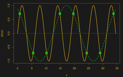 In sampling with an ADC, the frequency issue is more subtle: you want to pre-filter out all of the undesired frequency content that’s higher than half of your sampling frequency, because otherwise it folds into lower frequencies and messes up your data. The mathematical reason is the Nyquist-Shannon sampling theorem, but for intuition, there’s the wagon-wheel effect. When you’re sampling infrequently, “higher than half of your sampling frequency” is nearly everything, so there’s a lot to filter out.
The solution? Well, there are two. The first is to sample at more that twice the nuisance frequency and take averages in firmware. But when you’re already sampling really fast, or if the nuisance frequency is very high, that’s not an option. The analog solution is to get rid of the nuisance signals directly by filtering them away, and sampling just faster than twice the frequency of the desired signal. This is called lowpass sampling, and if you’re periodically reading an ADC without a filter up front, you’re lowpass sampling without the lowpass filter, and if there’s any strong higher-frequency signal mixed in, your resulting data is messed up. So you need a lowpass filter.
The other big difference between the PWM and ADC cases is that we want an audio waveform out of the PWM, which means a higher frequency AC signal, but in the ADC case we’re interested in the DC component of a low-frequency signal. Frequency range and AC/DC voltage offset will matter for the practical implementation of the filter, so it’s good to see both cases.
Filter Design Primer
There are at least five choices you have to make in designing a filter, and they’re all interdependent. When you add in other common pitfalls of analog design, like amplifier instability, range, slew rate, bandwidth, and distortion, parts tolerances, and real-world concerns like input and output impedance, it’s enough to drive you crazy. Here’s a whirlwind tour.
- Type: What frequencies do you want? Which do you want to get rid of? This determines whether you want a lowpass or highpass or bandpass filter, for instance. Today, we’re going for a lowpass.
- Topology: This is the actual circuit design. Here, we’re looking at a simple Sallen-Key filter topology because it’s stable and makes the lightest demands on the op-amp that we’re using. Even so, we’ll see that op-amp choice can matter.
- Order/Rolloff: The rate at which the high frequencies are rolled off depends on the order: the number of reactive components (here capacitors) in the design. You can make steeper filters if you need to by cascading single stages, and we’ll do that later. For now, we’ll be satisfied with a second-order filter that reduces the amplitude of the signal by a factor of four for every doubling of the frequency (a -12 dB per octave rolloff).
- Response: Some filter shapes over-emphasize certain frequencies and exhibit more overshoot or ringing in the time domain in trade for a steeper cutoff of the undesired frequencies. You can read more about that on your own time. Here, we’re going with a Butterworth response because it’s a nice midpoint between doing little damage to the signal and getting quickly to the eventual rolloff rate.
- Cutoff Frequency: The boundary between the frequencies that we want to keep (in a lowpass, the lows) and those we want to remove (the highs) is another important parameter that’s set by component choice.
A very good, if a bit advanced, resource on filter design is Chapter Eight of Analog Devices’ Linear Circuit Design Handbook. If you’re not feeling the math, you can skip the section on s transforms without losing out much. The remaining 140+ pages are pure gold, and should help get you through any analog filter design. We’re taking the expressway here, but if you want to enjoy the scenic route, go check it out. Filter Design in Thirty Seconds (PDF) is a quickie guide, and very much in the spirit of this series. It’s a great refresher once you’ve been through everything once or twice, but it naturally leaves out a lot of the good stuff.
Sallen-Key Lowpass: A Workhorse
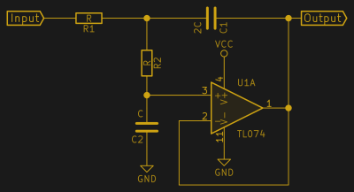
A generic filter design starts with at least the five choices mentioned above. I’ve chosen four of them for you, which leaves one dimension, and it’s entirely independent of the others. A second-order, Butterworth-response Sallen-Key filter is the Pareto-principle solution, giving you 80% of the benefit for 20% of the effort. Some configuration of Sallen-Key filter will work for most specifications, and we’ll handle complications like multiple stage filters and other circuit topologies for special cases later on. For now, here’s the basic circuit diagram.
The beauty of this circuit is that the two resistors can be the same, and they usually will be, but that they don’t need to be particularly tightly matched, so that component tolerances aren’t an issue. The two capacitors do want to be in roughly the correct ratio because this determines the response type, but again these aren’t critical and a simple way to get a factor-of-two capacitance is simply to use two of the same capacitors in parallel. Finally, the op-amp is used as a simple buffer or amplifier stage, rather than being implicated in frequency-determining gymnastics. As mentioned above, this places the minimum demands on the high-frequency gain of the op-amp.
Enough praise of the Sallen-Key topology, let’s build something practical.
PWM Output Filtering
Imagine that you want to produce an audio-rate waveform by PWM. Maybe it’s for sample playback, maybe it’s simple beeping or booping. The solution that you’ve perhaps seen before is to simply throw a resistor and capacitor on the output. This works, but has two drawbacks: the rolloff is only 3 dB per octave so there’s less attenuation of the higher PWM frequency, and it’s a passive filter which increases the output impedance across the board, making it quieter even for the low-frequency components that we want to keep. You could cascade two R-C lowpass filters to steepen the rolloff, but they interact and the circuit gets messy. It’s better to toss an op-amp in the mix and solve both problems at once.
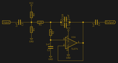 The product of
 C (here, the value of C2) and R determines the cutoff frequency, like so: . You have a lot of freedom in choosing the values. A good rule of thumb is to keep
R in the range of 500 Ω to 200 kΩ. I usually ballpark a C value for 10 kΩ and then pick a capacitor that works and fine-tune the cutoff frequency by tweaking the resistors until it’s right. For experimentation, two 50 kΩ pots or a stereo pot would be ideal.
Here, we’re aiming at an audio PWM, so ideally we’d set the cutoff of the filter around 20 kHz, at the top of human hearing. In an ideal world, our PWM frequency would be so much higher than 20 kHz that we wouldn’t have to compromise. In the real world, where we might be running PWM frequencies as low as 30-40 kHz, a cutoff of around 10 kHz is maybe a better goal. Plugging in 10 kΩ gives 1.13 nF. It’s almost too perfect! We’ll pick a 1 nF C and tweak the 10 kΩ if we need to fine-tune.
The ratio of the two capacitor values determines the response type of the filter. Again, we’ve settled on Butterworth as a good compromise, and because it makes the math easy. If you want other responses, your best bet is to dig up a filter design tool online to do the math for you. Ratios higher than two reach the cutoff rate faster, but exhibit frequency ripple. Ratios less than one roll off more slowly at first but have better impulse-response properties, or equivalently better phase linearity. Butterworth is the sweet spot for us.
Because this is an audio application, we don’t care about the absolute voltage, just the wiggles. An input capacitor decouples the voltage level of the microcontroller’s PWM and the pair of 100 kΩ bias the signal to the middle of the op-amp’s voltage range. An output capacitor decouples again, so the signal is ready to plug into whatever amplifier you’ve got. The values of these capacitors don’t matter much, but they have to be a lot bigger than C. I used 1 µF here.
Op-Amp Selection
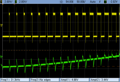
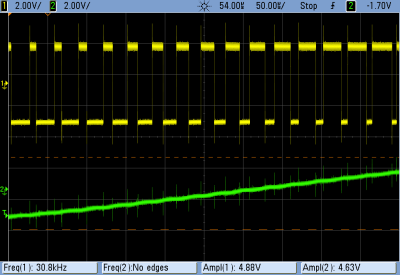
One of the reasons to choose a Sallen-Key filter circuit is that it’s easy on the op-amp. As drawn here, the op-amp is simply buffering the signal — it doesn’t have to manipulate any voltages in feedback to control anything. This means that if your op-amp has a frequency range that goes as high as the cutoff frequency, you’re good to go. I used garden-variety TL074s for this demo, and almost anything will work fine. I say almost because I initially tried an LM324 (which is the quad version of the popular LM358), and it choked on the square wave input.
In particular, the LM324 and LM358 have bad crossover distortion, so when the PWM input switches rapidly from on to off, the op-amp fails to track it. This shows up as nasty little spikes in the output. Some crossover distortion will be evident with any op-amp, but it’s especially horrible with the LM324. I generally love the LM324 because it’s cheap and works with input voltages as low as ground. We’ll use it below for slow ADC sample filtering, but its poor crossover performance makes it inappropriate for PWM filtering.
Anti-Aliasing, Pre-Sampling Filter
Let’s follow on with the example of a light sensor in the presence of flickering interior lighting. Imagine that we want to track per-second changes in light and smooth out the noise. As long as this is going into the input of a microcontroller’s ADC, we might as well scale the output to fit while we’re at it. Unlike in the PWM case, we care about the DC offset here — indeed, it’s what we’re trying to measure — so we’ll be directly coupling the filter to the output of the light sensor.
It may be a little bit odd to think of this as an anti-aliasing filter because of the low frequency, but the principles are the same — this is a lowpass sampling application. If we’re interested in detecting one-second changes, we can filter with a cutoff at 1 Hz and sample twice that fast, two times per second. The same idea works for sampling higher frequencies too, but the demands on the op-amp and the ADC get more pronounced. It’s better to start off easy. Here’s the circuit I have in mind.
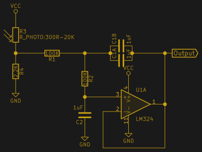 The photoresistor and 2.2 kΩ resistor form a voltage divider that’s dependent on the amount of light hitting it. (Pro-tip: If you want to pick an optimal resistor for any voltage-divider-like setup, multiply the maximum and minimum resistances that you’re interested in, and take the square root. The result, the harmonic mean, is the lower resistor value that you want.)
I wanted a cutoff frequency around one second for this filter, so I initially ran the math with a 10 kΩ resistor, and got 10 µF — too large for my liking. Scaling the cap down by ten and the resistor up by ten is just about right. Because we’re interested in the DC values, simply drop the input capacitor and bias resistors and the output blocking cap.
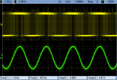
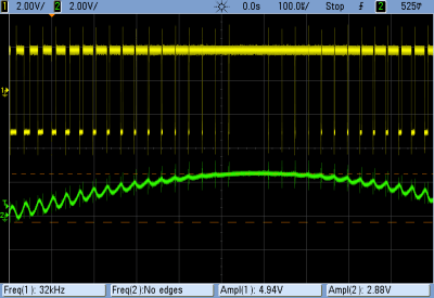
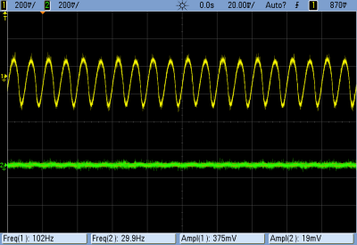
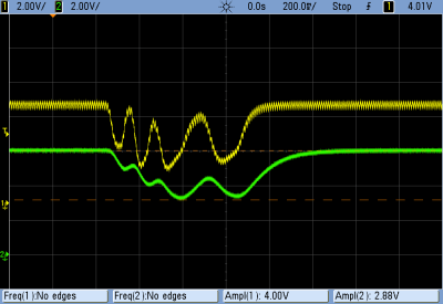
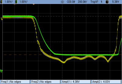
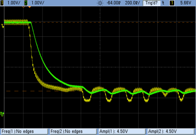
From these scope shots you can see the desired action of the lowpass filter. In the left pane, the noise from the fluorescent light, which sits around 330 mV peak-to-peak, is filtered out nicely down to the twenty-millivolt level. In the right pane, you can see the response as I wave my hand slowly over the sensor, simulating a range of lighting levels. (I have four fingers!) The value tracks the actual light level reasonably quickly, although you can see some delay between the unfiltered and filtered values. This is just what happens when you filter!
Op-Amp Selection, Again
As opposed to the PWM application, the TL074 fails us here while the LM324 shines. The TL074, among many other op-amps, is designed for use with a negative voltage rail, which means that it can’t handle input signals that get within a couple volts of the lowest voltage. Here, where we’re using ground as the negative voltage reference, this causes the amplifier to miss out on input signals below about 1.5 V as I wiggle my hand up and down while covering up the sensor. The LM358 picks up these changes.
Picking op-amps for any application is full of nuances. I picked two of the most standard and representative types for this demo. The TL074 is decently fast for an old part, which makes it good for audio, but it’s designed for dual-supply use so it doesn’t cope with low voltages reliably. In audio (AC) applications, you usually only use the center portion of the voltage range anyway, so that’s OK. The LM324/LM358 is slower, but uses less power and reaches down to the negative rail on input, which makes it good for low-frequency, battery-powered, DC signal conditioning. When you need both rail-to-rail operation and high speed, and then you tack on low noise and low power consumption, you’ll find yourself reading datasheets and making tradeoffs, or spending money.
Matching to an ADC
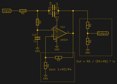 The last detail to prepare a messy analog signal for digitalization is to scale the output voltage up or down to match the voltage range of the ADC. As it stands, the wire between the output and the inverting input on the op-amp holds the gain at 1. It’s a simple matter of adding two resistors in feedback to amplify the resulting signal, or adding a voltage divider following the filter to scale the signal down. Naturally, you only want to be doing one of these two.
What’s Next?
If you’ve followed along this far, you’ve got a general purpose lowpass filter that will handle almost all of your lowpass filtering needs: it’s got a decent rolloff, is capable of working with DC- or AC-coupled signals, and it’s got adjustable gain so that you can squeeze the maximum precision out of your ADC. You can even tweak the response type by changing the ratio of the capacitors if you want, but that’s getting fancy.
Next up will be three more examples of the Sallen-Key filter: a highpass design just swaps the resistors and capacitors, and a very useful bandpass filter can be made by cascading a highpass with a lowpass. Higher-order (steeper rolloff) filters can also be made by cascading these stages.
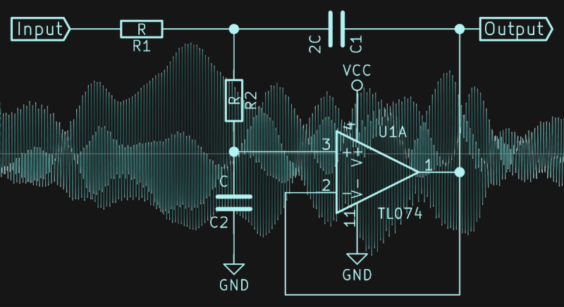
(Beautiful background image in the banner from [Windytan]’s phosphor-effect script.)



That was awesome! I’m active on diyaudio.com and have been contemplating making active crossovers for my speakers to use with small Class D amplifiers. I appreciate the intro to filters.
The book suggested in the article would be a better resource for you as audio (the human ear) is more sensitive to phase. Digital circuits by the most part can completely ignore phase error.
Um, Isn’t that the other way round (our ears cannot hear small changes in phase). From my reading the limit is around a couple of ms of group delay is inaudible in an audio system.
I never knew opamp can affect the filtered output tremendously. Thanks for the scopeshots!
Beware of slow opamps like LM358 and LM324. Their feedback loop is to slow to react to square wave and their output impedance is higher close to GND and VCC. If you apply strong CMOS signal from i.e. CPU, its input will saturate every cycle. To avoid it increase input resistor and lower the capacitor to maintain bandwidth. Or install simple lowpass RC filter before active one.
Having come from the analogue era, I would suggest that you don’t even bother with the really old op-amps. Probably, the only reason that they are manufactured and used today is because there are so many *old* circuits out there that people follow because analogue design has become somewhat of a lost art.
Modern op-amps are thousands of times better on some metrics compared to these old chips.
If you want an instrumentation amp then you want very low input offset and a modern chip has 1/1000000th of the offset of some old chips.
If you want a sh!ty old audio amp to drive 0.25W into a 1″ beeper then use an old chip like these if you want.
The op-amp side is simple. They are just an impedance buffer that has two undesirable qualities 1) DC input offset which is amplified as much as the desired signal and 2) a maximum slew rate (maximum frequency). Just buy one that fits your requirements.
There is no magic sauce in the filter. Filters are complex to analyze for other forms of electronics but they are dead simple for digital signal (pre-)conditioning.
All you need to know –
1 (simple) filter is 3dB per octave, 2 (simple) filters is 6dB per octave. A simple filter is a resistor and capacitor as a divider.
T=C*R, your time constant or corner frequency is simply the capacitance times the resistance.
This covers *most* digital situations because in digital the blocked frequency is almost certainly much much higher than the desired frequency range. Things only become complex when the blocked frequency is within an order or less of the desired frequency.
400kHz to (or from) Audio 20kHz is more than an order (of 10) different.
What you *do* need to know is the frequency components of a square wave –
Damn, I was going to link a Wikipedia page but the math there is over-complicated.
In *simple* terms. For a square wave (50% duty cycle) the frequency components are the original clock and a reducing proportion of each odd harmonic (integer multiple).
For a PWM signal that is *NOT* 50% duty cycle, you have two basic components –
A (higher) frequency of twice the period of the shorter part and a reducing proportion of each odd harmonic
AND
A (lower) frequency of twice the period of the longer part and a reducing proportion of each odd harmonic
So for a 1kHz PWM at 25% duty cycle your principle components (not including harmonics) are 750Hz and 4kHz
For 8 bit PWM the extremes 255/256 of clock and clock * 256
long post – probably some errors – polite corrections welcome
Corner Frequency and Cutoff Frequency seem to be interchangeable terms now –
https://en.wikipedia.org/wiki/Cutoff_frequency
forget the sh!ty Wikipedia math because we want f and not w
Corner Frequency = 1/(2 * PI * R * C)
Time constant
https://en.wikipedia.org/wiki/RC_time_constant
Time Constant = R * C
see how hard that was lol.
To be fair, most “old” circuits can use newer op-amps fine. After the 741 they became much cleaner, no external compensation needed, except for the ones that did, but a standard form.
The 709 was a “hot” device for a while, but always needed external compensation, I recall a capacitor and resistor.
Earlier IC op-amps were worse, no standard compensation and maybe pinouts. I once found some uA702s in a box of junk I brought home, mid-seventies I think, and when I looked them up, they were completely useless.
About 1976 there was a wave of new devices like the CMOS RCA CA3140, better specs but not better gain-bandwidth, soon followed by the TI biCMOS op-amps which were better, but others soon were way better.
But some devices are easier to get, thus they get used (or viçe versa), so just like 2N3906s are still specified, 741s and 324s still see use. But using better opamps in those circuits shouldn’t be a problem, though may not show improvement in that circuit.
At least the LM3900 has faded. I’m sure it had its uses, but it was grabbed mostly because it could run off a single ended supply, before devices better suited for that came along.
Michael
Roll-off for simple RC filter is actually 6dB/octave
https://en.wikipedia.org/wiki/Roll-off
Yep, correct. I was thinking about the 3dB points for corner or cutoff frequency.
Also the 6dB per octave is actually dbV (volts) and not dBP (power). dB is most often used for power.
[quote]Probably, the only reason that they are manufactured and used today is because there are so many *old* circuits out there that people follow because analogue design has become somewhat of a lost art.[/quote]
The old op-amps are still very useful in education to show people the limitations of those devices and the difference “perfect op-amp in simulation” – real world. At university we had some special made boards with the good old 741 for this.
Why not passive?
Passive filters are OK if you have a consistent driving impedance and a consistent output impedance. They also introduce loss. But if can stand some loss and have well qualified input and output Z’s passive filters will do ya. As an aside, they are also tricky to build in multiple poles because of the above. People have been known to stick op amps between them just for the impedance transformation.
Passive filters are more of a ‘doable’ thing now for inputs on many of the modern AVRs as their input impedance is in the order of 100s of kOhms or even MegOhms.
To anyone interested in filtering audio, opamps, amplifying audio, etc… I can’t say enough good about Douglas Self. I recommend starting with “Self on Audio” 3rd Ed (http://amzn.to/2nfUE3w) or, if you already have intermediate aptitude, “Small Signal Audio Design” 2nd Ed (http://amzn.to/2mk9B5r).
I’ll just leave this here:
http://www.ti.com/lit/an/sloa096/sloa096.pdf
This one even has design worksheets for beginners…
http://www.ti.com/lit/an/sloa093/sloa093.pdf
What’s interesting about both of these is that they have two op-amps for a band-pass or notch filter.
There is no need for a second op-amp if you can calculate the complex impedance.
If you wanted, one op-amp could simultaneously be a low pass filter, high pass filter and integrator.
TI has Filter Pro V3.1as a download, see https://e2e.ti.com/support/development_tools/webench_design_center/b/elabblog/archive/2010/10/29/filterpro-v3-1-available-now?keyMatch=filterpro , requires login, but well worth it!
+1 The TI application does suggest minimum GBW for the selected OpAmp. But there are myriad other factors involved that only experience on the bench will help with.
I see lots of mentions here of old op-amps to be avoided and their many pitfalls.
How about some recommendations for modern op-amps that are widely sourced and avoid such pitfalls?
There are so many out there that it’s probably overwhelming to find them so just google for what you want.
Some Spec comparisons –
   TL074, ISL28134

  8 mV  , 2.5 uV   : Offset Voltage

 18 mV/C,  15 nV/C : Temperature Coefficient (Input Offset)

100 dB  , 135 dB   : Common Mode Rejection Ratio

  3 MHz , 3.5 MHz  : BandWidth
The ISL was found by googling ultra low offset op-amp and it’s offset is 3000 times lower and it’s drift is 1000 times lower. This is what you want for accurate high sensitivity measurement of very small signals.
TL074…
With an input common mode range that doesn’t include ground.
For every beginner or hobbyist, do yourself a favor and stick to rail-to-rail opamps and single-ended designs only.
i like those diagrams, could you tell me please on which software are they made?
I have been designing an antialiasing filter for a data acquisition circuit just like this article mentions.I was going to use a simple RC filter. One thing I just found out about an RC low pass filter is that you don’t need a center analog ground. You can attach the capacitor to battery ground or even positive voltage. I think a high pass filter you would need an analog ground but the low pass you don’t. My circuit is battery powered and splitting the battery voltage would add parts. I’m trying to keep the parts count down and the circuit size small.
How well will my design work with an RC filter attached to battery ground?
An anti-aliasing filter is always a low-pass filer so it intently has a DC path from sampled voltage to input.
If you sampled voltage is DC and above the sampling reference ground and less then the analogue Vcc then you done.
If the sampled voltage is AC then you need to create a false reference or split rail voltage. This can done with a couple of resistors and the circuit modified so that these resistors form part of the RC network.
If you were using op-amps anyway then you can use an extra op-amp to the split rail reference to reduce the current consumption or even use the already in-use op-amp with some trickery.
one thing I like about those quad opamps is that most have standard footprints so you can try different kinds without rewiring.
I’m not sure I understand what is happening with this circuit. Is the filter circuit on the input of the IC being used to select a frequency range then the opamp inverts the phase and reinserts it on the other side of the cap to null the unwanted high frequency noise?
Hand-wavingly, that sounds right, although I’ve never seen it presented that way. (In college, you get the math…)
There’s kind-of a lowpass on the input and an effectively high-pass (the capacitor + the input resistor?) in the negative feedback loop. I guess I buy it.
Hi, Thanks for the great articles. I really like your type of explaining the topic!
In combination with the short and informative sallen key sessions from ADI at YouTube it helped me a lot to understand the background and now im getting quite good results on my filter design.
But I´m a bit lost on the fact how resp. where to bias my filter+amplification to vcc/2 correctly to use the entire ADC input range. As your articles explain, it should come at the output of the filter stage, but if I apply this at my circuit the opamp is only clipping i(6th order AAF by .8dB Chebyshev characteristics) not matter where I apply the bias voltage.
I appreciate any help you guys can provide!
greetings!
This is a great article! It really helped me understand low-pass filters and build one! I’m using it to get rid of interference from a 24v a/c motor. As you can imagine, the interference is the dreaded 60hz cycle. I’m using a LM358 with 100k Ω resistors and 1 µF capacitors. Poof! No more 60hz interference. The only thing I might add is that, if the output of your op-amp is mostly in the range of your A2D chip, but just goes above the A2D chip max input limit occasionally, or under certain conditions, then you can use a Zener diode to clip the voltage and thereby protect your A2D chip. Obviously, you’ll need to make sure that the voltages which you’re interested in are already in the range of your A2D chip before clipping it. In my case, as long as the cable is connected, the voltage range is between 0 and 4.8 volts. If the cable is disconnected, then the voltage will go up to 15 volts, which is the source voltage for the circuit I’m measuring with the A2D chip. Therefore, clipping using a 5.1 Zener diode, with 2% tolerance, is perfect for me because the A2D chip can only handle 5.3 max volts.