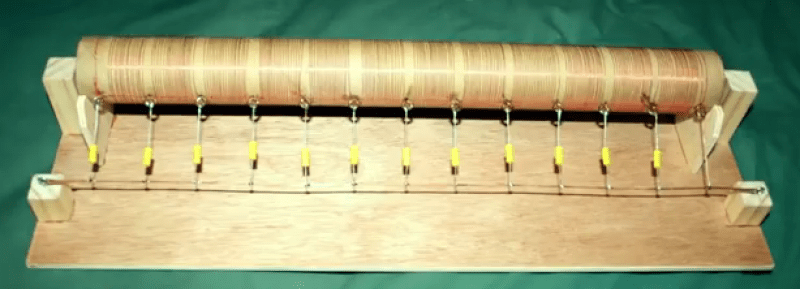
Transmission lines are the kind of thing that seems to confuse beginners. After all, the fact that short-circuits can have infinite impedance and open-circuits can behave like a short is not intuitive at all!. That’s why we like [Tinselkoala]’s latest video that shows a nice model of a transmission line. It helps to understand the line as inductors and capacitors in series-parallel connection.
Any pair of wires used to transmit electrical power have tiny amounts of inductance and capacitance. This is not a problem with DC or low-frequency AC, but when the frequency is sufficiently high, weird things start to happen. The energy tends to escape as radio waves, and current reflects from discontinuities such as connectors and cable joints. For this reason, transmission lines for high frequency signals use specialized construction to minimize those effects and reduce power losses.
[Tinselkoala] has built a model of a transmission line using coils and capacitors to simulate the inductance and capacitance of the line, with LED’s placed between the coils. He feeds the system with the signal generator with frequencies from 10 kHz to 1 MHz. In his words, they act as simple “visual voltmeters” to show the peaks and nodes of the standing waves of voltage in the line.
It is relatively simple to build your own version if you want to experiment with this fascinating subject. You will only need some magnet wire, capacitors, resistors and LED’s. If the subject sounds interesting to you, here you can find an excellent introduction to transmission lines.


Cut out the middleman. Just attach the high frequency to an eight foot strip light. Drop the voltage until it’s borderline glowing. You’ll see a standing wave.
May as well use a skipping rope if that is all you want to see. This shows the TL as it is represented in diagrams when you do the theory.
I like it but he should have started with a stationary wave then explained why it moved. I suppose it is because it isn’t really a “why” video, more just “howto”
I do enjoy this wired version. Delay line memory was always one of my favourites, especially the quartz crystal type, you’d usually find inside the odd tv or vcr.
I wonder how long I could make one of these. (:
Awesome… :O
There was not only the ~64µs (1 TV line) glass delay line), there was also the 330ns delay line, to compensate for group delay differences due to the much smaller bandwidth of the color channel compared to the the luminance channel. The 330ns looked quite similar to a miniaturized version of the coil in the top picture, just without extra capacitors. The capacitance of the windings to the metallic coil former was enough. The coil former must have been slotted to prevent eddy currents.
But now this stuff is as dead as analog TV.
My father once told me about the mercury delay line memories he worked with in the ’50s. A different world…
cool.
I like it. Good job.
In all my years as a electrician I’ve never seen this.
I wish they had this in electrical school.
Another good model: https://www.youtube.com/watch?v=DovunOxlY1k
This is still one of my favorite demonstrations of wave behavior. I bought the book many years ago.
I spent 12 years testing and isolating trouble on transmission lines. This is a great explanation of how it works. A pipe organ and a pair of wires behave almost identically at lower frequencies I don’t have any experience with anything above 40k cycles/sec though.
sorry for the report, I really meant to hit reply.
Awesome video, nice find!
Fantastic! Thank you for sharing! So much to think about… Just boiled years of theory down onto some pretty practical ways to help describe why it’s important to have a balanced electrical system.
That’s awesome! Very cool, nice work.
This was great :) Very informative.
The first thing I thought of when I saw the image was the vertical delay lines used in old Tektronix ‘scopes. They delayed the vertical signal enough that you could see the point on the waveform that the sweep was triggered on. Back in the ’80s I used to work on old Tek ‘scopes I bought at Hamfests and then resell them in working order. My father showed me how adjust all the little trimmer capacitors so that a square wave was actually represented as a square wave (of course other signals would be distorted too, but not as obviously as a square wave). Normally they didn’ have to be touched, and it was smart not to, but sometimes a previous “technician” would “tighten them all up” Later solid state ‘scopes were fast enough that the delay line was simply a coiled piece of coax, but the old tube ‘scopes needed more delay. My father was a field service technician with Tektronix.
I think it will be very confusing for some people. What’s never mentioned, is that the standing waves are the result of the signal being reflected at the end of the transmission line. At each point, the sine wave meets a reflected version of itself, and the time it takes to travel to the end and back, will determine the phase shift. E.g. if it takes half a period to travel to the end and back, the reflected sine wave will be shifted 180° and thus be inverted. At this point the two waves cancel. If you measure at a point where it takes one period to travel to the end and back, the signal and the reflected signal will have the same phase, and thus they will amplify.
Design of transmission line is an important factor that one should consider to save energy loss from the electric circuit.