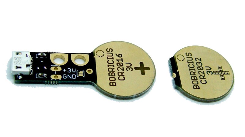
The Coin Cell Emulator CR2016/CR2032 by [bobricius] homes in on a problem some hardware developers don’t realize they have: when working on hardware powered by the near-ubiquitous CR2016 or CR2032 format 3V coin cells, power can be a bit troublesome. Either the device is kept fed with coin cells as needed during development, or the developer installs some breakout wires to provide power from a more convenient source.
[bobricius]’s solution to all this is a small PCB designed to be inserted into most coin cell holders just like the cell itself. It integrates a micro USB connector with a 3V regulator for using USB as an external power source. The board also provides points for attaching alligator clips, should one wish to conveniently measure current consumption. It’s a tool with a purpose, and cleverly uses the physical shape of the PCB itself as an integral part of the function, much like another of [bobricius]’s projects: the Charlieplexed 7-segment LED display.


At first glance I thought it was a PCB key…
Am i the only one who feel this is over engineering a non problem?
Yes.
It ain’t over engineered enough, It needs to be powered from a nuclear power plant with 12MW dumped into a massive liquid hydrogen cooled current shunt that has 3v across it worked out from Ohms law to get the correct shunt impedance.
Where will the other 500MW go? I know… to power the “massive liquid hydrogen cooled current shunt”. Your idea is starting to sound a lot like biofuels.
Giant air conditioner to cool the polar bears of course!
I think it could be useful, but… it doesn’t seem to fit regular CR2032 battery holders!
Yah, I see about 99% flat mounted 1% vertical.
Its meant for metal cage/tab type holders, not the plastic molded ones.
http://www.klsele.com/admin/product_upload/201205101631331321405501KLS5-CR2032-09B.jpg
Why would you (not “you” you, “one” you) use a quarter Dollar, the size of which only USians have a fair grasp on, instead of, say … a coin cell???
There’s a solution to the ambiguity which frustrates you so: “Why would one use a quarter Dollar”
Because it’s the stock image from a Chinese manufacturer’s website… duh…
just do the conversion, it’s about the same size as a 22 euro cent coin
Yup, it’s overegineered. If I had to du any prototyping using coin cells, I’d just solder some wires instead…
You must not work in the toy industry. :) I’ve done four projects running off of coin cells this year, so far. We were ordering LR44s 250 at a time, almost every month, for a while. While this wouldn’t work for every step of the development process, as we do need to account for the current limits of the actual cells, this would save us /tons/ of money during the bringup stages.
Then maybe do some damn implementation with a silly little LM317 t
Can’t you just solder two wires to the battery contacts and connect them to a lab power supply with voltage and current set to emulate the battery, including internal resistance?
I’d be like, hmmmmm, 2 zinc carbon D cells, close enough… still last a hundred times as long at least…
How are the alligator clips used to measure current? Is there a way to break the series circuit?
Probably a tiny current sense resistor, if you’re feeding it from usb you’re not going to care about a little bit of loss
the next step would be to copper plate the sides of the pcb for those irritating coin cell pockets that have contacts on the sides.
one option could be to just dip it in conductive paint and get a uniformal coat on all sides.
It is useful, but I would add it needs an pluggable/extensive/whatever for the part of coin cell connector. As in, an adapter so this can be connected to other form factor sockets, like those in pc motherboards.
Does anyone want it turned the other way, pumping out 5v from a coin cell!
Plate the side of the disk and add an SMD 2 pin header on the top surface instead of the PCB sticking out the side and you can use it in a lot of normal products and battery holders as used on motherboards etc.
Note that this is actually a patented concept, so tread carefully. (I unfortunately can’t find the patent number offhand)
How can it be? Dummy batteries have been around since the 60s at least.
Found it. US8564939. Silly what people can get patents for these days.
Don’t coin cells have very high resistance? Shouldn’t that be emulated too?
Well, I have no opinion about this thing but a big ole “up your nose with a rubber hose” to the jerks that somehow thought soldering a battery in place was a practical option for something that needed to be changed.
Or welding.
I really like the idea, but I wonder if this does miss the boat on designing how battery failure conditions are handled. There’s an opportunity to simulate different power conditions with this emulator that doesn’t exit with a normal coin battery.
Value added opportunity!
now someone just needs to design digital calipers that don’t eat alkaline coin cells like candy
Seriously, how are they eating more than a watch or calc when they’re off most of the time.
Buy mitutoyos and they will last. Or buy cheap Chinese and accept that they won’t.
“Off” isn’t that off.
It just turns of the display, the measuring circuit remains active. So turning it off reduces the current draw by 2% or so.
How much more would a real swirch cost?
Less than a battery or two i bet
That’s obnoxious. Hmmm might see if I can cut a slot in the battery cover to slide a little plastic tab in and out to break contact.
Its only the cheap ones that do that. Poor design. A Mitutoyo will last quite a long time before batteries need replacement. It just costs more for initial purchase. For my needs the cheap pair worked well but it was a hassle for the batteries to be dead every time I needed it, so i spent the money on the Mitutoyo.
I considered buying one, until I saw it is 300€ (and that’s current promo price). That so extremely exaggerates as a price. There has to be a good option with a reasonable one.
This only “emulates” voltage, and it is target for development. The same thing can be achieved by a pair of wires as mentioned before.
A true emulation should consider the discharge voltage curve and the impedance model for the desired battery.
If the goal is to save the time that takes to solder 2 wires, well done then.
+1
Where is the flux capacitor version of this?