High Current Measurement Probe For Oscilloscopes

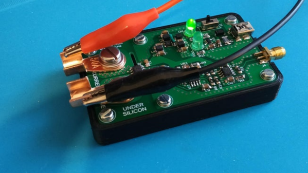
A decent current measurement sensor ought to be an essential part of every hacker’s workbench. One that is capable of measuring DC, as well as low and high frequencies with reasonable accuracy. And bonus credits if it can also withstand high bus voltages – such as those found in mains utility or electric vehicle work. [Undersilicon] couldn’t find one that ticked all the boxes, so he built an ACS730 based AC/DC current probe capable of measuring up to 25 A at frequencies up to 1 MHz.

Allegro Microsystems has a wide offering of current sensor IC’s. The ACS730 features a -3 dB bandwidth of 1 MHz, and -1 dB bandwidth of 500 kHz. Since it is galvanically isolated, it can be used in AC mains applications up to 297 Vrms and for DC up to 420 V. And as he intended to use it as an oscilloscope accessory, the analog output suited the application nicely. A pair of precision op-amps provide the voltage output scaled to 100 mV/A. The board is powered off a 1000 mAh LiPo battery that can run the sensor for about 15 ~ 20 hours. The power supply section consists of a charge circuit for the LiPo, and a split rail dual output power supply converter for the op-amps.

The ACS730 has a 2.5 V output when measured current is zero, and is scaled for 40 mV/A. This gives an output voltage swing from -0.5 V for -50 A to +4.5 V for +50 A. This is where the AD823ARZ dual 16 MHz, Rail-to-Rail FET Input Amplifiers step in. One pair is used to obtain a 2.5 V reference from the 5 V supply, and also to buffer the analog output from the ACS730. The second pair subtracts the 2.5 V offset, and applies a gain of 2.5 to get the 100 mV/A output. Dual power supply for the op-amps comes from a TPS65133 Split-Rail Converter, ±5V, 250mA Dual Output Power Supply. Lastly, LiPo charging is handled by the MCP73831 Single Cell, Li-Ion/Li-Polymer Charge Management Controller.

Initial testing of direct currents has shown fairly accurate performance. But he’s observed some noise when measuring currents below 1 A which requires some debugging to figure out the source. [Undersilicon] has provided the CAD files for both the PCB and 3D printed enclosure, giving you access to everything you need to build one yourself. If you’re looking for something a bit more heavy duty, you might be interested in this +/-50 A, 1.5 MHz sensor encased in concrete.

Current Measurement With Oscilloscopes

What do a Rogowski coil, a magnetic core, and a hall effect sensor have in common? They are all ways you can make oscilloscope probes that measure current. If you think of a scope as a voltage measurement device, you ought to watch the recent video from Keysight Technology (see below). It is true that Keysight would love to sell you a probe, but the video is not a sales pitch, just general technical information about making current measurements with an oscilloscope.

Of course, you can always measure the voltage across a shunt resistor — either one that is naturally in the circuit or one you’ve put inline just for measuring purposes. But if you add a resistor it will change the circuit subtly and it may have to handle a lot of power.

The Keysight video points out that there are different probes for different current measurement regimes. High current, medium current, and low current all use different probes with different technologies. The video is only about 6 minutes long and if you’ve never thought about measuring current with a scope, it is worth watching.

The video shares some high-level details of how the current probes work — that’s where the Rogowski coil comes in, for example. Of course, you can’t expect a vendor to tell you how to build your own current probes. That’s OK, though, because we will. Current probes are often expensive, but you can sometimes pick up a deal on a used one.

Continue reading “Current Measurement With Oscilloscopes”

Hackaday Prize Entry: A PCB To Emulate Coin Cells

The Coin Cell Emulator CR2016/CR2032 by [bobricius] homes in on a problem some hardware developers don’t realize they have: when working on hardware powered by the near-ubiquitous CR2016 or CR2032 format 3V coin cells, power can be a bit troublesome. Either the device is kept fed with coin cells as needed during development, or the developer installs some breakout wires to provide power from a more convenient source.

[bobricius]’s solution to all this is a small PCB designed to be inserted into most coin cell holders just like the cell itself. It integrates a micro USB connector with a 3V regulator for using USB as an external power source. The board also provides points for attaching alligator clips, should one wish to conveniently measure current consumption. It’s a tool with a purpose, and cleverly uses the physical shape of the PCB itself as an integral part of the function, much like another of [bobricius]’s projects: the Charlieplexed 7-segment LED display.