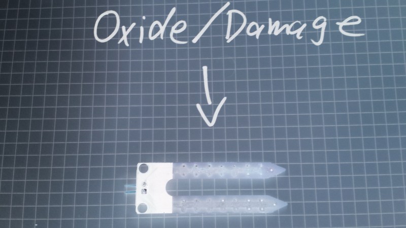
If you compulsively search online for inexpensive microcontroller add-ons, you will see soil moisture measurement kits. [aka] built a greenhouse with a host of hacked hardware including lights and automatic watering. What caught our attention among all these was Step 5 in their instructions where [aka] explains why the cheap soil sensing probes aren’t worth their weight in potting soil. Even worse, they may leave vacationers with a mistaken sense of security over their unattended plants.
The sensing stakes, which come with a small amplifier, work splendidly out of the box, but if you recall, passing current through electrodes via moisture is the recipe for electrolysis and that has a pretty profound effect on metal. [Aka] shows us the effects of electrolysis on these probes and mentions that damaged probes will cease to give useful information which could lead to overworked pumps and flooded helpless plants.
There is an easy solution. Graphite probes are inexpensive to make yourself. Simply harvest them from pencils or buy woodless pencils from the art store. Add some wires and hold them with shrink tube, and you have probes which won’t fail you or your plants.
Here’s some garden automation if this only whet your whistle, and here’s a robotic friend who takes care of the weeds for you.


Wouldn’t running the sensor only occasionally to check (i.e., one second every couple of hours) also be a way to prevent the electrolysis oxidation?
I find it hard to believe that these devices that a lot of people have been using for years are that unreliable and this one guy has the solution.
Never just one solution…maybe one that’s best
There is also a problem with fertilizer and temperature, this causes a lot of sensor errors.
A capacitive sensor has a lot more accuracy and it doesn’t spike with fertilizer. Catnip industries made one for a few bucks on tindie that is pretty good and speaks i2c. I don’t think you could archive this with a resistive sensor.
Probably not…capacitive sensors are fairly stable
AC can’t be used for electrolysis iirc so swap current direction on each reading. Graphite might be cheaper than the circuitry required though.
National Semiconductor’s ’78 Linear Apps handbook had an AC moisture detector. I’m off-grid and have fought with a related issue – water tank level detection, for a few decades now. Especially if it’s heated water…almost everything fails, from magnetic-actuated reed sensors with a magnet in the float, to optical, to sonar to..it’s a long list – either oxidation or scale gets them all, except for the ones that are simply eaten away. I built a level sensor for my living quarters with a 555 (yup, in a house full of SBCs.) and some other simple stuff, and it’s been working around 5 years now, no issues at all. It uses the 555 to drive a long titanium wire at the bottom of my cistern with around 12v, ac coupled, at around 40khz. I have 4 other Ti wires coming down from the top to different depths, and each drives an ac coupled voltage doubler (.1 uf caps, 1n4148 diodes) which drive a 100k load, then directly fed into cmos logic (uno or esp8266). It just works. Ti doesn’t easily electrolyze, but in this case with AC..it’s perfect year in and year out, with rainwater which isn’t always so pure. Changed to an analog readout, this would work as soil moisture too, and I plan to do that as well for my garden.
Rain water in your living quarters, I must be misunderstading something? You make it sound so easy, I’m not even sure I want to ask for pictures it might shatter the simplicity of you explanation. :-)
With AC titanium is a little overkill :-) stainless steel or normal copper should work perfectly – like for the water pipes
I had the same issue with my rainwater tank. Tried them all, but a dirt cheap sonar sensor with its electronics covered below a layer of hot glue is still working perfect.
We’ve been using an ultrasonic range finder wired to a networked Raspberry Pi to monitor the water level in our sump pit for 3-4 years now. The only failure has been a bad solder joint. No corrosion on the sensor.
Yes AC is the way to go. I have a bunch of cheap moisture indicators (3pc for 7,95), where the sensing electrodes are completely covered with soldermask. Because they use capacitve sensing.
But they can not be (easily) used together with another microcontroller. They are self contained with a CR2032 and a string of LEDs for indication.
link please?
I bought them at http://www.pollin.de https://www.pollin.de/p/digitaler-feuchtigkeitsmesser-dfm-70-3-stueck-863318
unfortunately the price increased a little, but 9,95 is also not bad.
I can see the bare edge of the PCB, so I don’t think I’d trust these for long-term use left in the soil.
“AC can’t be used […] so swap current direction”
Swap current direction? You mean… alternate the current?
The circuitry required is exactly one capacitor.
This is the way I did it in the 90s.
uC –> capacitor —->peg in soil.
Keep pin low for a while,
Tri state the pin with pull-ups enabled.
Time how long it takes the tiny cap to charge, ie how long it takes for the pin to rise.
Short time = dry.
long time = wet.
And the p[ins are capacitively coupled, so no DC current can be flowing.
In practice uC pins should not go off board without some protection from stray currents. But that applies no matter what sensor you are connecting.
And the problem still is – the cap pins are metal.
If you have: metal, electricity, and a ground medium, you’re going to leech metal ions and corrode/destroy the metal.
That’s why graphite is the best solution here.
Agreed, graphite plus AC sensing. The issue with DC is not what it does to the electrode but what it does to the ions in the soil. If you do DC measurement you eventually pull the positively charged ions disproportionately towards the negative electrode and the negatively charged ions towards the positive electrode at which point the measured conductivity will be artificially low until you reverse polarity. AC measurement prevents this problem provided your frequency is high enough (in the 10s of Hz or so).
I totally agree. After thinking about setting up some auto-watering system today (DIY) this thought came to me. Sure electrolysis happens, but if I charge the sensors for 1 second every few hours, I see longevity. Of course there are 100% bogus sensors out there off the shelf. Gotta look out for that, but the graphite rod idea is interesting. I will talk to my local nuclear plant, see if they got anything laying around.
Any chance with the local nuclear power plant? Just need a return of experience before i go ask mine!!
That problem was pointed out here on HAD ages ago and the response was dismissive at best.
Now consider this, what if they have a swept AC signal put through them and you are measuring changes in impedance? That and gold plating should do the job. Also you only have it active for a very brief period every hour, not continuously or more frequently.
The gold AND the ac AND the sweeping AND the low duty cycle seems like overkill
Also plant in glass bead substrate and water with de-ionised water….
deionized water is probably terrible for plants.
Use probes soaked in fertilizer
But only one of them is overkill.
0 AND 1 AND 0 = 0
So not overkill overall.
Anything conductive will get eaten away in soil. The moment there is a pinhole in the gold plating, it will eat away quickly without any outside source of current necessary.
Is there really even a reason to have them powered up to do a check more than once a day? I’ve never known a plant to die in a single day from soil conditions that were satisfactory the previous day. Is soil sensing even needed period other than the hey look what i can do factor. People have grown house plants for ever without crazy control gadgets. Just set an arduino to dispense a measured amount of water into the plant once a week. figure out how long it takes your pump to dispense a cup of water. set the dispensing function to only turn the pump on for that amount of time once a week. Done!
Stop making sense.
open loop control vs. closed loop in essence.
Agree, there’s just no consensus and I’m about giving up and doing it by hand as I done for ever.
Just can’t find a decent capacitive circuit with reliable instructions and I don’t want to use my arduino.
Facts!
All the ideas involving using AC or only checking once a day miss a crucial point – those tin plated copper traces would eat away stuck in the ground, anyway.
Yup, particularly at the air/ground interface. Titanium works well, stainless steel might be OK too. McMaster has Ti.
Note, just sampling a DC drive now and then probably won’t cut it. Even your signal ground might not be ground and may have some electrolysis current…
Titan wires are available in diy jewlery stores, and in bulk for welding TIG/MIG/PLASMA, what thickness would you prefer? Titanmetal in bulk is 10€-100€ per KG, and easily available wire is about 400€ per KG here, so ~10€ per meter
Then use capacitors fro AC coupling.
That is why I mentioned gold plating, a common PCB manufacturing option. Even with titanium you still want to avoid generating a Ph gradient in your soil due to DC current. Mix some plant food with gelatin and Ph indicator and you will literally see what I mean when you put a current through it.
Unless you want to actually pay the additional cost of plating the side of the PCB (round edge plating) moisture ingress into the PCB will happen and your copper will be eaten up from the inside out.
I don’t even think that would work. FR4 is hygroscopic. Even if you plate the entire thing, the underside of the copper (against the PCB) is still exposed to water. Properly waterproofing the thing with exposed contacts is going to be really hard.
Gold plating can be eaten away, too, by electrolytic corrosion.
AC seems the obvious solution to electrolysis problems.
Stick something metal in the ground, it will corrode away. No source of current available. Differing concentrations of various things in the soil mean the pH levels vary from point to point on the metal. Differing amounts of corrosion on the metal from point to point plus the pH levels varying make galvanic currents flow through the metal, accelerating the corrosion.
Galvanic corrosion does not require two wildly different kinds of metal.
Don’t even need an art store. I think most Staples still stock the leads for drafting pencils.
You’re still doing it wrong! With capacitive sensing, you don’t need the conductors in direct contact with the water or soil at all.
That’s the real way to go. Dip the sensor assembly or PCB in thick paint or glue and use AC.
i played with that a bit … yes the sensor does not degrade, but it is very sensitive to the position in soil and soil contact. You can move it a bit and produce a readout that has more dynamic range than the dry-wet range in a fixed position. I used one similar to these (no association with the shop) https://www.tindie.com/products/miceuz/i2c-soil-moisture-sensor/
If anyone has a better solution that is not so sensitive, it would be cool to know.
measure the weight of the plant and pot
works for indoor but how do I weight my garden?
It would be a logistical nightmare considering the multitude of ways pots are mounted. Not to mention expensive.
How do you compensate for the weight of the plant’s leaves, roots and stems, which may increase rapidly during the growing season (or decrease when it drops dead leaves or flowers)
…….there is so much violence in this world…..
It’s good to see the Hackaday community can all agree on one thing: you’re doing it wrong.
If there’s one thing that two engineers can agree on, it’s that the third one is doing it wrong.
B^)
It seems like just yesterday we solved this problem. ;)
And for connecting to graphite rods, here https://hackaday.com/2009/12/20/better-resistors-from-a-pencil/
When Hugo Gernsback started selling wireless kits in the early 20th Century, he was using pencil graphite for resistors. A number of customers complained their kits weren’t working. He found out his “supplier” had no consideration for electrical resistance when mixing graphite with clay before firing them in a kiln. They worked something out.
Yeah, I keep telling people, pencils can be quite conductive BUT, test every pencil. Then ppl go “Oh you need high quality pencils then?” No,no, nonono, TEST.. EVERY…PENCIL. … in particular if you want one for modifying values of surface mount resistors or to close bridges that would be far too delicate a job with solder, go round up every pencil you’ve got and test for lowest resistance across lead, and for resistance about 1/8″/3mm apart on a patch of “scribble” on paper.
Oh and if it says polymer lead, or wood on pencil looks like that woodpulp plastic, don’t bother with that one.
Sounds like IKEA is the place to go for DIY repair kits then.
Some are conductive enough that applying about 30V on a pencil sharpened at both ends made it smoking heavily and finally split the wood apart :-) Of course it produces copious amounts of heavy, tarry smoke and chars the inside of the wood. Do it outdoors.
Try Carpenter’s pencils from the hardware store. They are fat and usually #2 type media.
Might have to look into this I’m in the process of making a hydroponic control system, which will require moisture sensing, I was contemplating using a combination of techniques, only Sampling periodically, using an AC signal and now maybe incorporate carbon or titanium probes.
Sensing what moisture? If your system is hydroponic, you’re basically running water nutrient solution to your plants roots all the time anyway. There are some systems that shut off the pump for some time to allow the roots to “breathe” for a bit, but a fixed timer can do that just fine. What you need to monitor is your waters PH and EC levels to make shure your plants have enough food.
I used galvanized steel for moisture measurement in my automatic watering system, worked fine :)
Heavy pieces? How long? How do they look now? Galvanized steel is just zinc plated. The zinc is a sacrificial metal, buried in soil it is going to eat away pretty fast. And add zinc oxide to the soil. As soon as it is mostly gone, the steel will rust.
The article is saying that sensors like Chirp have an electrode problem, too. But this is totally wrong since the electrodes are totally isolated and covered with solder resist. They measure the soil by measuring the influence of the soil to the capacity between the two “electrodes”. So this “problem” is one, that is solved for years if you’re looking for a good working, long-life and cheap soil sensor…
Or am I missing something crucial here?!
The only problem I see with the Chirp sensor is that as the top of the sensor is at the soil/air interface, it may give unreliable readings.
I have been using capacitive sensing of soil moisture levels and fluid tank levels for many years. The key to soil measurements is to have the sensing plates completely buried so they can’t be bumped and they aren’t in the last 1/2 to 1 inch of soil where the moisture varies rapidly.
http://www.polyphoto.com/tutorials/ElectronicCircuits/Dual555CapMeter150dpi.jpg
Stick two insulated probes into the soil and watch the capacity vary with the moisture. Since the isolation is constant, you only have to determine the point at which you find the soil dry enough for watering. No current will flow, no probes mades of unobtainium have to be used.
I worked in an Electrical Engineering Department here in Australia many years ago where one of the lecturers patented an electronic leaf for watering. The unit pumped a precise amount of water into a humidity chamber with an absorbent pad over a resistive sensor. This was designed to maintain 100% humidity in the chamber. The chamber was covered in Gortex so as the water evaporated they would dose it again, each time measuring the total water delivered. The next step was to place these electronic leaves near a particular crop to characterise the leaf against that crop. I think they sold it to wineries of a golf course or something.
“wineries of a golf course”, now that could be a profitable, though limited market!
B^)
The comments on this article are cool but most are related to solve a secondary problem which is the oxidation of the sensor. The real problem here is to measure humidity.
When you got stuck tring to solve a problem I advice to take a look at a free Effects Database, which can provide a shortcut or at least new ideas (link: https://www.triz.co.uk/how/triz-effects-database)
By the way, the rotted out carbon rods in my warm mist humidifier say that neither AC or carbon/graphite makes it immune to deterioration either.
Agreed. AC just means that the electrolytic removal of material happens mostly evenly across both rods, not that it stops it or somehow replaces atoms.
Carbon rods have very peculiar behavior in water. Attach a.graphite rod to each lead on a multimeter. Immerse those leads in saline. Cnnect a DC source across the leads, outside of the water and measure the voltage. Then remove the DC source ..
In fact, all normal conductors have strange behavior in water due to double layer effect. Carbon is especially weird because it has a high surface area and a multitude of energy storage modalities.
This is called polarization, a bit like charging an accumulator.
Only to be avoided by using an AC system. What can be as easy as using an 74HC14 and some passives (and diodes). One inverter forms an Oscillator ~1kHz, this connects through a coupling capacitor to the “feeder” electrode in the tank or through separate coupling capacitors (100nF ceramic is fine) to one electrode in each flower pot.
The other five inverters can be used as five separate detectors. Each one gets an input stage like a voltage doubler made from one double diode like BAV99 and to 100nF capacitors. One cap couples to the sensing electrode and the other is a smoothing capacitor at the input of the inverter, in parallel you connect a 100kOhm resistor. This gives a time constant of 10ms.
Of course you can also use a microcontroller, at best with schmitt trigger inputs instead. But this is more effort because it needs software to work.
Use fully isolated (coated) parallel metal plates inserted into soil and measure capacity between them. Needs some calibration, though.
Capacitive is the way to go.
Pressure sensor, measures weight of pot, when it’s too light you water the fracking thing, no electrodes, wooo wooo wooo!!! :-P
And as the plant grows, you water it less and less…..
I think weight against time, as water is evaporated, you’d have a curve that flattens, and since nobody uses anything less than a microcontroller for such things now, you program it to see where the curve is flattening out, rather than having an absolute value for minimum weight.
Let’s Rube-Goldberg this baby!
The plant sits on one end of a teeter-totter. On the other side is a counterweight equal to the plant, pot, and moist soil. As the water evaporates, the teeter-totter moves which opens a needle valve until equilibrium is achieved. An ultra-long-term “hourglass” next to the counterweight pours out fine sand at the same rate as the plant grows mass. Every time the “hourglass” is empty, the counterweight is reduced to account for a heavier plant. Also, there should be a bunch of rolling marbles and some dominos at one point.
It’s so simple!
In seriousness, using weight is a pretty solid plan.
Electrolysis isn’t a problem here as the currents involved would be trivial; microamps pulses are more than enough to detect soil resistance and using AC would work even better. The real concern here are those sensors which aren’t built to prevent oxidization: they soon start to conduct less and less electricity to the point the soil will appear dry forcing the automation to water the plants when there’s no need to, thus is killing them. All those sensors are built using PCBs and they all are junk. Inox metal should be used, probably even aluminium would work provided it is cleaned regularly.
Aluminum instantly forms an insulating oxide coating in oxygen atmosphere.
Stick it in water, and changes in pH from point to point will cause galvanic corrosion.
Put an insulating coating on it and measure capacitance/impedance.
A tensiometer is the best solution since it actually tells you if the plant wants more water than is available, but they can be a bit fiddly. Failing that, local weather readings and evapotranspiration calculations (and possibly a drainage allowance depending on soil type) with a margin of error should give good enough water replacement behaviour.
You are correct in saying that a tensiometer is probably the best tool (currently available) for determining when to irrigate in an automated system. However, what a tensiometer actually measures is soil moisture tension (matric potential). In layman’s terms we can use tensiometers to determine how much water is plant available in a given substrate for a specific zone. It does not tell us anything about what a plant wants or needs. Vapor pressure deficit (VPD) is another metric that is often overlooked and equally important to greenhouse environmental control.
The real problem with garden automation projects here and elsewhere is that engineers are neglecting to talk to scientists. I say this as a scientist who dabbles in engineering.
AAAND!
(This is actually a thing that buggedd me on day one when I saw those things)
Nickel ions are not good for your plants in those quantities, copper certainly isnt…
a few years ago i also wanted to do an electronic watering system but then i figured out that you don’t need electronics at all. there are solutions with clay cones that act as hygroscopic valves and pumps. google for blumat for example.
You have really greatz ideas. Didnt know about the capacitive sensing and will look into that.
To the guy saying plant moisture doesnt change within a day: Some plants are grown at high efficancy and need the best care they can get.
And my Hydroponics system with 5 tomato plants was using 15Liter of water a day. I know , not really comparable but dont underestimate the thirst of a plant at full growth.
Flooding the plant and wait till its dry isnt a great solution. It just keeps your plants alive.
I’ve tried the clay cones, but the roots surround the cones and the rest of the soil was dry and not used at all.
Stainless stell or gold plated electrodes might work, but i try to keep low budged.
Also apology, if i missunderstood the Chirp. I just used as example fur the copper electrodes. seems like they do it right
My solution to indoor use would be to put a scale under the pot(s) and measure total wieght of the pot. This way one gets closed loop control. One can also then add some nueral stuff and let the system learn from you. First stage is to let the system monitor you watering the plants by operating the pump manually and then set the system to fall back to auto pilot if you are absent.
typical tech-centric oriented “solution” to a something perceived as a problem, that creates more problems itself (and does not solve the real problem itself), without understanding for the underlying biology system dynamics.
It is not question about how much moisture the is in the soil as much as how much the biology life in the soil can retain moisture and how much they need and that is not something that can be resumed.
A cheap solution for keeping the biology life moisturized and such to plan irrigation, when on vacation (and not only at that time), it to just put a clay pot(s) with water in the soil, next to the plants, connect that pot with a soft plastic tube to a bigger water reservoir (if needed, of course the 2 water levels need to be the same), and the biology life and the plants will pull as much water as they need from the porous clay pot(s), and the tube will pull that water form the reservoir in order to equalize the water levels. It is a self balancing system that will work without and supervision, as long as there is a water in the bigger reservoir, and the auto refinement of the last one is a trivial task.
exactly!
much better than any solution with electronics.
there also are versions which don’t need reservoirs but where the clay pot acts as a valve.
Weighing the plants has a big problem: The majority of the atoms in the plant come from the air. Very little comes from the dirt. And as it grows, the plant contains more moisture, which means more weight in the plant.
Grow a cactus instead
You can find graphite rods from old alkaline batteries too, a little work but the rod in alkaline batteries is thicker, sturdier.
Love this comment, thanks loads !!
If you are doing small project for potted plants, then these are good enough, for crops or hacker farms, better to use vinduino’s gypsum moisture probes.
I think too much of dependence on technology for farming is not good. We should avoid fertilizers which kill our soil productivity.
good day sir! may i ask if how many moisture sensors can be used in a vertical aeroponics system and why? thank you
I think that the voltage provided by a micro-controller would be low to start electrolysis?
It absolutely IS enough to cause electrolytic decomposition of the metal. Boats have a large hunk of zinc because anything just in contact with the water will cause electrolytic decomposition without any voltage applied. This is called a sacrificial anode. It gets eaten away rather than any other metal at or below the waterline. It will have lost a considerable portion of its mass by the time it is replaced.
Large ships have huge power supplies so that the sacrificial anodes are DEFINITELY the part that gets eaten away.
If you bury a piece of stainless steel, it will cause its own electrolytic decomposition just because the soil is not amorphous. Some parts will be in a slightly more acidic or basic environment, causing a difference in electrical potential, causing current to flow and for parts of the metal to be eaten away.
My idea was using AC. I think needs to be REAL AC (swapping poles, not just turning current on and off). A 555 chip could generate an alternating square wave, but it would need a series capacitor to one of the electrodes in order to get true AC.
I actually think the idea of using a graphite electrode is much simpler and more elegant. Pencil lead has been suggested. Also a carbon rod can be extracted from a dead zinc carbon battery. Zinc carbon batteries are not very common nowadays, but they still exist.
Or, you know, you could use carbon fiber rods that won’t snap if just look at them the wrong way ;)
This actually doesn’t solve the problem. The minerals in the soil are still going to build up on the probes and lead to less and less accuracy over time.
It may prolong the use of the sensor but by no means is this a final solution to this complicated problem.
I like the AC approach. Does making a circuit w/ shift register to pulse several sensors make sense to you? I’m thinking six probe connections (3 pairs). Mix their input through an integrator for an average. Compare the average to the cross-sections of the three pairs.. (Identify “zones”?) –I may be the “third one that got it wrong..” (Maybe, just put a daily dose on a timer…?