
Traditional desktop 3D printing technology has effectively hit a wall. The line between a $200 and a $1000 printer is blurrier now than ever before, and there’s a fairly prevalent argument in the community that you’d be better off upgrading two cheap printers and pocketing the change than buying a single high-end printer if the final results are going to be so similar.
The reason for this is simple: physics. Current printers have essentially hit the limits of how fast the gantry can move, how fast plastic filament can pushed through the extruder, and how fast that plastic can be melted. To move forward, we’re going to need to come up with something altogether different. Recently a team from MIT has taken the first steps down that path by unveiling a fundamental rethinking of 3D printing that specifically addresses the issues currently holding all our machines back, with a claimed 10-fold increase in performance over traditional printing methods.
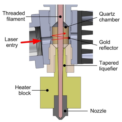
As anyone who’s pushed their 3D printer a bit too hard can tell you, the first thing that usually happens is the extruder begins to slip and grind the filament down. As the filament is ground down it starts depositing plastic on the hobbed gear, further reducing grip in the extruder and ultimately leading to under-extrusion or a complete print failure. To address this issue, MIT’s printer completely does away with the “pinch wheel” extruder design and replaces it with a screw mechanism that pulls special threaded filament down into the hot end. The vastly increased surface area between the filament and the extruder allows for much higher extrusion pressure.
An improved extruder doesn’t do any good if you can’t melt the incoming plastic fast enough to keep up with it, and to that end MIT has pulled out the really big guns. Between the extruder and traditional heater block, the filament passes through a gold-lined optical cavity where it is blasted with a pulse modulated 50 W laser. By closely matching the laser wavelength to the optical properties of the plastic, the beam is able to penetrate the filament and evenly bring it up to nearly the melting point. All without physically touching the filament and incurring frictional losses.
There are still technical challenges to face, but this research may well represent the shape of things to come for high-end printers. In other words, don’t expect a drop-in laser hot end replacement for your $200 printer anytime soon; the line is about to get blurry again.
Speeding up 3D printing is a popular topic lately, and for good reason. While 3D printing is still a long way off from challenging traditional manufacturing in most cases, it’s an outstanding tool for use during development and prototyping. The faster you can print, the faster you can iterate your design.
Thanks to [Maave] for the tip.


That’s still pushing plastic through a single nozzle, which requires rapid movements and lots of noise and energy.
The obvious solution is to borrow from inkejt printers where the ink is pumped out by a piezoelectric element vibrating against a hole:
https://www.therecycler.com/wp-content/uploads/2013/06/piezo.jpg
An array of these pumps can deposit a line of molten plastic, which is swept over the area to be printed. You can either scan it, or rotate the whole nozzle to keep a continuous motion.
That’s still raster based though and I don’t think most people grasp the limitations of piezo jetting anything higher than almost water viscosities. To put it simply, jetting things that are over even a few hundred cps just doesn’t really happen, let alone molten plastic that is probably easily measured in the 100,000+ cps or even higher range. Plus, the volume per piezo movement is going to be measured in picoliters so the volume is going to be very small per activation. It activates quite frequently but not that frequently to even be able to remotely compete with jetting spools of material out.
But that’s precisely the way Objet printers work.
Yeah but the objet printer use fluid photopolymer not thermoplastics
https://www.engineering.com/3DPrinting/3DPrintingArticles/ArticleID/14219/WACKERs-ACEO-Brings-Silicone-3D-Printing-to-the-Public.aspx
At least one industry group (possibly Picsima as well) has somewhat recently managed to figure out how to print thixotropic materials at least. Unclear what the printhead is like exactly but that material seems to be printable. Which is pretty impressive considering the viscosity.
100 micron thickness. Unclear what the print times are likely to be exactly but they are not going to be quick.
Curious how the process differs from traditional methods or if it is actually even PZT based technology.
Not at all. It squeezes a fluid rather than molten plastic. Huge difference.
One doesn’t need to propel the plastic out of the hole, just pump it out of an array of nozzles. It doesn’t need to be piezoelectric either – just the principle of locating a small actuated pump at the nozzle to dispense a small amount of plastic.
The resolution too can be arbitrary, as you can angle the array as you sweep it. You don’t need to have x lines per inch, because when you put the array at an angle, the individual nozzles squeeze closer together as viewed from the direction of travel.
I know of no thermoplastic that has the viscocity and droplet formation characteristics needed… all thermoplastics that are solid at room temperature, have high viscosity when melted… Id love to learn of a structrally sound plastic (at room temp) that has the viscosity needed for piezeo droplet formation when melted… anybody know of one?
It doesn’t need to form droplets, just pump the plastic out of the nozzle.
Another alternative is to block the nozzle by a piezo actuator against the feed pressure, to stop the plastic from flowing out, but that has the added complication that closing off one nozzle increases flow at all the others.
Pumping the plastic out is sort of what current extruders do now though. How would you maintain a consistent “laminar flow” out of the nozzle as well as consistently be able to start and stop flow? Molten plastic is typically injected (at rather high pressures), not really pumped out.
That is the million dollar question. It’s a control loop challenge, because you need to maintain the right pressure at the feed to match the number of extruder holes open, and there’s a slight lag between the two because there’s a pressure reservoir between the feed of molten plastic and the nozzles. Placing the (extra) pumps at the nozzles reduces the control loop problem. Another way is to maintain a sufficient overpressure at the feed so the individual nozzles have a proportionally smaller effect on it, but then you need fine control over the nozzles.
It would be extremely convenient if you managed to design a micro-sized pressure regulator for molten plastic.
https://www.youtube.com/watch?v=TyNYNyPjkqU
No idea what that “ink” is made of but it seems to turn to plastic when exposed to UV, pours like water in its unexposed state, and is something you only want to deal with if you have to.
Beyond a huge number of photopolymers that are room temperature solid but jettable at an elevated temperature the most useful substance to jet of all….WAX. From solvent dissolvable, to water soluble, to more durable waxes similar to those used in dental and jewelry modelling. The main limit to what can be done are patents held by 3dsystem blocking the xerox multijet head and ones owned by stratasys through their acquisition of solidscape IP. While FDM is nearly open and free, and photopolymer resin printers patents expiring or sidesteppable….Jet modelling is still largely locked away from the law abiding…..unless you can afford to pay
Basically you’re right: sticking with filament isn’t “fundamental rethinking”. Nice detail improvements for sure, still fundamental improvements need fundamental new ways of depositing build material.
Piezo extruders are one way to consider, there are more. Like granule extruders, like electrostatic deposition (paper laser printers use it), like variable size nozzles, like bonding pre-deposited material.
I thought the logical way to speed up printing was – add prefabricated material.
The occasional layer of honeycomb steel mesh, for example, would reinforce walls and reduce the need for internal bracing.
How would you print around stuff that’s already there? Or do you mean to leave space for the other material to be added after printing?
threaded filament, that is simply genius !
The XYZ movement was never the problem, I have seen plenty of XY tables move that fast, the problem was always the extruder.
Movement isn’t really the limitation in the XY direction, it’s acceleration. High accelerations are needed, otherwise the high travel speeds are useless. High acceleration means all sorts of problems with vibration and accuracy and your machine needs to be more rigid (read: more expensive) so it doesn’t rip itself apart. Just look at that monster gantry in the video. I’m pretty sure it’s not just for fun, it has to be built like that. And you can still see it vibrating in the video even then.
Not saying it’s impossible, but a printer is gonna have to be built like a tank to support the kinda speeds in the video.
A two staged gantry could have a short range/high frequency actuator for “just the tip ” and a classic gantry for global positioning. Then again that add cost and complexity.
if you have an extruder the has a better grip to the filament then you don;’t have that problem. The hobbed bolt I’ve made for my own 3D printer really eats his way into the plastic.Essentially creating it’s own threads. The problem is really in the fact that you need to push so hard to get the filament through the nozzle.
I’m pretty sure that having threaded filament will eventually result in the same feeding problems, most likely because the filament is damaged in some way. Simply because it is easier to have a damage the thread on the filament then damaged the threads of the hobbed bolt.
A concern I have about putting more plastic through the nozzle, simply means that you need better cooling, because you introduce more heat, you’ve got to remove the heat to prevent collapsing the print under it’s own weight. We’ve all been there when we wanted to print some very tiny objects. And our systems didn’t have super-duper-laser-heaters that could heat 10 times faster. If you look at the video you see a huge transparent pipe that generates the cooling air.
Although it is an impressive machine… it’s still a single nozzle system, which simply is the real bottleneck.
+1
My home brew printer has fair bit of wobble in XY plane which limits speed and quality but even that when pushed by things along “stripping” fillament does occur occasionally and causes more trouble than a bit of wobble
Just what we need. Patented (thus pricey, perhaps single-source) filament, one color only filament so it’s tuned to the laser, print heads that become ray guns when the laser falls off.
I’ll pursue UV resin printers, thank you. Lasers and one color but higher resolution, etc.
Yeah it seems like the laser is overkill here. 808 nm will be variably absorbed on the type of filament (and doesn’t necessarily correlate to filament color in the visible) this solution seems to result in more expensive filament and more limited range.
The advantage of the laser here is the ability to dump a large amount of heat into the filament very quickly and throughout the volume of the filament. There’s got to be another approach? Maybe a radiative ceramic tube heater?
+1
I think you might underestimate the impact of a broadband light source like a radiant heating element. This is research after all, removing competing variables from the study (ie wavelengths) is very much in the interest of the study. For a professional 3D printer where you pay for the supply chain and certification of materials (and are locked into a few specific materials sold by that company), correlation of the laser power to filament type isn’t much of an issue. (nor is an extra $10k for the laser to a $750k machine)
That being said, the real question is how long it will take these results to be duplicated for consumer printers. I suspect there are a lot of creative ways to simplify and reduce the cost of this setup without serious reduction in performance, but you’re going to need a very well built and capable machine to handle those kinds of speeds while producing anything worthwhile.
Higher costs too.
Probably not compared to threaded fiber, a 50 watt pulsed laser, and all of the exotic materials described for the print head.
Why pulsed? Pretty much the only reason pulsed laser are used for engraving and cutting is Q-switching, which results in a shorter, but more intense pulse, so that the material ablates instead of just melting…
How could the screw drive filament be patented? It is obvious and have been used in (at least) other mechanism for feeding.
Not that I’d be surprised if you did get a patent of an obvious design, there are so many crap patents out there hindering real innovation :(
The US patent system will grant pretty much anything (barring extreme obviousness). The reason is that the USPTO is not responsible for a patent’s legitimacy, accuracy, viability, or (most importantly!) novelty. Don’t get me wrong, the patent officers do a lot of work, but it’s not their job to do your due diligence or check your freedom to operate.
Basically, if you are willing to pay for it they will grant it, BUT you’d better be willing to fork up the money to defend that patent from infringement or a lawsuit challenging it.
Seriously, I’ve seen patents with Microsoft paint drawings that have less detail than kindergarten drawings. I’ve read one (from a prominent US Med Device company) that read like it was originally written in English, then translated into Swahili, then to Chinese, then to Spanish, and then back to English and then read out loud by a 4th grader with that unintelligible Louisiana-Creole accent.
I’m not sure I see the advantage of heating the plastic using a laser versus just heating the glass with a resistive heater and in turn the plastic? It seems like the glass would act like a heat sink with the current arrangement and would actually cool the plastic that the laser has worked so hard to warm.
I think the best way to speed up 3d printing is with a software-controlled variable diameter nozzle. This way, walls and infill can be printed fast with a 1mm equivalent, and outside walls and details can still be preserved.
Multiple printing heads are the obvious way to improve speed. Parallelism for the win!
Proper design (stability), better extrusion control and faster/more precise head movement would help too but increases the price a bit. More hardware, better sensors, better control electronics and better software = $$$.
The laser is to reduce friction compared to the hot end.
threaded filament and laser heating doesn’t sound like it will end up in sub-$1000 printers…
Considering that a 60 watt co2 laser tube is like 80 bucks for the no name, and 150 for the name brand ones. Add in the front reflecting gold mirrors, quartz chamber, and that the thing has to be threaded? It’s got to be very expensive, probably cheaper to build a second printer than to make one of these for anything other than single monolithic projects.
I really want to see the finished part, and see what the layer bonding and surface finish are like. Not to mention I really want to see what they think is a reasonable enclosure for this monster, considering the laser it’s using.
“The extrusion and heating mechanisms are contained in a compact printhead that receives a threaded filament and augments conduction heat transfer with a fiber-coupled diode laser. The prototype system achieves a volumetric build rate of 127 cm3/hr, which is 7-fold greater than commercial desktop FFF systems, at comparable resolution; the maximum extrusion rate of the printhead is ~14-fold greater (282 cm3/hr).”
Fiber-coupled diode laser so it doesn’t appear to be asking that much especially when concentrated in a small area.
So hugely more expensive, but safer. And it’s not going to be happy with a heated chamber unless you water cool it too.
How are fiber coupled lasers more safe? Either the machine is designed and built with adequate protection or it’s not.
In fact, the fiber coupled one is probably worse on the safety, as it’s most likely NIR or visible, meaning it WILL get to the retina, unlike 10um CO2 lasers, which would not…(It would still cause pretty bad injuries, but modern medicine can fix those, busted retinas are currently unfixable)
These are pretty cool developments – a nice fresh take on the engineering. These speed improvements will have to come with fundamental material changes, too. The normal bonding, cooling, and shrinking of plastics will become the next obstacle.
Bonding being the most important part IMO. Smarter extruders that can pre-heat (potentially also post-heat) previous layers for improved adhesion to the newly extruded plastics could help a lot.
Not that interesting… how about print heads that tilt and can print in different planes (or even not in a plane).
How about a print head that measures the object below. I.e. printing on an existing print.
Printer scans object, adjust model to match object, print with 5 axis.
How about a print head that measures the object below. I.e. printing on an existing print.
Printer scans object, adjust model to match object, print with 5 axis.
Let’s start with slicing software that can make use of the fact that the z-axis can be coordinated with the X and Y and therefore not need to slice everything in to piles of 2D prints.
Back in the early days of reprap the first extruders used a screw thread alongside the filament (not around the filament), which apparently had great grip but had a tendency to twist the filament entering the extruder after a while. I wonder what measures these guys are taking to prevent that. (e.g. see http://reprap.org/wiki/ThermoplastExtruder which pre-dates the reprap darwin)
This used only one screw, I wonder if you could have 2 screws along the filament to push in opposite directions. ONe of the big draw backs is not knowing how much plastic is coming out of the extruder.
So running a stepper would be needed
1980s called…
Nowadays we have cheap servos at our disposal – more torque, more efficiency, less size and weight, more precision and actual feedback. Steppers should be forgotten, just as selsyns are now.
i was just thinking about this a bit more. We would need 2 screws one left handed and one right handed, running in the same direction
It seems that with the screw-alongside-filament design, one could add a second screw with left-handed threads. Then the torques would cancel out.
I’ve often wondered why only the hobbed gear was driven, why not pinch the filament between 2 rubber or similar material rollers and have the movable roller be connected to the motor shaft with a gear set so it is also pulling, not dragging? Running threaded filament through a tube seems more difficult then it needs to be, is the tube a threaded hollow shaft in the stepper motor? and yeah how do you counter the drag of the threads on the filament?
I must be misunderstanding something here, why would the drag have to be compensated?
I don’t follow you. How do you have “drag” on the pinch wheel or the threaded tube, they are the driving elements in the system.
Do you mean friction?
Rubber wears out too quickly, not to mention that the teeth on the extruder gears don’t rely just on friction, they actually press groves into the filament.
Yes rubber rollers would wear out but so do hobbed bolts, it just seems rubber or poly rollers would give better control, when dealing with paper or plastic rollstock in high speed wrappers or printers both rollers were almost always powered in my experience. Drag is friction yes in that the pinch roller is using some of the energy from the motor to turn, the more tension you have on the pinch roller the more friction will be present while your dragging the pinch roller along with the filament and hobbed bolt. If your running threaded filament through a threaded tube what force are you applying to the filament to keep it from just spinning with the tube instead of creating pressure in the head? One of the two needs to rotate and the other needs to be kept from rotating.
Yo hackaday folks, please remove this dupe.
No. He is right on. It’s good to hear another perspective. Otherwise we only hear our own drivel until we believe it’s true
No, Mike, it’s a duplicate comment of the one above it :-)
All that concludes to larger surface screw drive around filament and preheating for filament. I’m pretty sure both of these ideas were implemented long ago industrially.
Non-driven pinch gears (or axial groove cutting wheels, or something better) to hold the filament from rotating axially, then a thread die bonded in series with a nut to cut threads into filament and drive filament at the same time. A certain amount of torque will be required for thread cutting.
A long enough preheating section above the final heating block to bring filament just under melting point. This setup might be long so Bowden tube probably a good idea. Heck, why not just make the Bowden tube the preheating section? PTFE melting point is much higher than common filaments. And… we don’t even need to reach their melting point.
Instead of making the filament expensive, adding a one time cost to the machine is always better. My humble opinion may be buggy. But if it’s not crossing with any patents, I’ll be happy if someone tries it.
*correction…meant to say glass transition temperature instead of melting point.
What about RF heating for the preheated filament stage?
Aware that different plastics deal with RF inputs in different ways but guessing they’d be less ‘picky’ than one tuned to a specific wavelength of light.
This addresses the wrong problems. What you really need is faster post-extrusion cooling (without adversely affecting layer adhesion). Faster heating is easy, and extrusion was never a problem.
That just demonstrably false. Did you read this post? Or the original article it references?
The first step in this process was identifying the bottlenecks and targeting them specifically, and they are showing up to 10x improvement. So how could it have not been a problem?
Even cooling is mentioned as something else they need to look into, so there’s really no merit in your comment at all.
I didn’t read either… Also, what they identified as bottlenecks isn’t necessarily what others regard as the bottlenecks. And showing improvement is easy if there’s room for improvement to the current standard to start with (CF the other recent paper).
Meritless comments are a fundamental foundation of the internet as we know it. I’m proud to be contributing.
If one wants to double the speed of a print, then couldn’t one have two nozzles?
Yes, two nozzles wouldn’t give a 2x speedup, nor could everything make use of the two of them.
Easiest way I can see to implement a two nozzle setup that is at least a bit more flexible in what it can do, would be two have two nozzles on the same axis, but independently driven along that axis. Though, getting them to not crash, and making build paths for the machine to effectively use the two nozzles would be a project in it self to create.
Another method could be to have a heater block that has more then one filament. Simply that it has for an example 4 extrusion holes evenly spaced, each feed by its own motor. As long as the pitch between the individual holes are known then it shouldn’t be too much of a challenge, other then not having it clog up around 4 times faster.
But even this method wouldn’t halv the print time, even if it can lay down 4 times as much plastic per second, it would only be better for filling in larger areas, something a printer isn’t always doing.
I was thinking about two nozzles too.
Even if they move independently Their paths should still overlap. Otherwise where the two paths meet you get a seam that will tend to fall apart.
If their paths overlap than avoiding collision will be tricky.
I was thinking maybe just forget about independent movement. Think of the multi-nozzle setups we already have for multi-color, support material, etc… What all nozzles were loaded with the same kind of filament and the slicer was smart enough to take advantage of that fact. It would try to optimize the path so that both (or all 3, 4.. x) nozzles are over places that should have plastic at the same time and just extrudes them simultaneously.
Of course there would be sections that need to be extruded by one nozzle where no other nozzle is in a useful position at the same time. So… as the number of nozzles increases to X you will not get 1/X print time. Still… it would be an improvement.
2 nozzles = good; 1 big+ 1 small ( for teh fine detail ) used one at a time as needed. Slicer optimisation is the constraint.
Want to maximise speed & reduce the acceleration forces ? go delta.
Oh wait, the reprap community done those already….
further optimisation is variable slicer thicknesses ( certainly for the infill where you cant see the finish….
It kinda reminds me of a miniature injection molding machine only without the mold.
Why no mention comparing the speed and acceleration rates to the delta design? Those Cartesian designs have issues with moving lots of weight around at the head besides the melting limits of hotends. The new extruder they have looks like it might have lightened up the head a bit but the laser adds some back too.
The other thing is if they were really talking about speed, why demo something with so many small segments and therefore requiring so much acceleration and decelerations? Straight lines and showing mm/s measurements compared to other machine speeds would be more informative. Unless this is really more academic than practical so data relative to existing machines gets left out…
You don’t need fucking threaded filament for a screw flow design!
cross threaded filament (filament thread manufacturing error ECT>>>>…..) will invariably result in more plastic build up in the receiver than the combination of a tapered threaded receiver & smooth filament
Bottom of the linked article says it all, “This research was supported by Lockheed Martin Corporation.” So this is a paper justifying a research grant and explaining why they need a new grant to do more research. They say in the article that the printhead is “about the size of a computer mouse” but what we see in the video appears to be the same size as most printheads and we never get to see the top so we do not get to see the whole thing. Sounds similar to that “vibration algorithm” for 4 times faster print speeds from last month. Skimmed a few of the other videos on that youtube channel and it seems like a bunch of hype with not much progress for consumer grade printers.
Fiber lasers are starting at 2-3k usd (20-30W power)
I always wondered how long fibre lasts – given the amount of movement. Why not mod a cartesian laser cutter to warm the print head? No fibre wear, & a small(ish) extruder head. Need to raise & lower the table though.
The problem isn’t the printer, it’s humans and their need for more speed, no matter how fast something is we’ll still want it faster.
That depends on the problem people are trying to solve. If all that is desired is something to make prototypes or hobbyists’ low volume personal production then more speed would be nice but certainly not a necessity. We can make do with what we have. On the other hand if you desire 3d printing to become a bulk manufacturing method without the need for expensive retooling… the state of 3d printing really is a problem. A problem that may very well be impossible to solve!
60 seconds to procreation. :-) Seriously making things faster shortens the prototyping cycle.
MIT earned my facepalm… 🤦🏻♂️ Nova Hotend does the same thing without any fancy unusable in practice crazy things.