It’s a great time to be a hobbyist. No matter how you feel about the Arduino/Raspberry Pi effect, the influx of general enthusiasm and demand it has created translates to better availability of components, a broader community, and loads of freely available knowledge. When people have access to knowledge and ideas, great things can happen. Tools that were once restricted to industrial use become open source, and the price of entry-level versions goes into a nosedive.
As we’ve seen over the last several years, the price of cheap 3D printers keeps falling while the bar of quality keeps rising. It’s happening with laser cutters and carving tools, too. Strolling through Microcenter a few weeks ago, I spotted a new toy on the back wall next to the 3D printers. It was LinkSprite’s desktop mini CNC. They didn’t have one out on display, but there were two of them in boxes on the shelf. And boy, those boxes were small. Laughably small. I wondered, could this adorable machine really be any good? To some, the $200 price tag suggests otherwise. To me, the price tag made it justifiable, especially considering that the next price point for a hobby CNC mill is at least twice as much. I took my phone out and stood there frantically looking for reviews, documentation, anything that was available. It seemed that the general, if sparse consensus is that this thing isn’t a total waste of money. Oh, and there’s a wiki.
According to LinkSprite’s wiki, this little machine will engrave wood, plastic, acrylic, PVC, and PCBs. It will specifically not engrave metal (PCB copper notwithstanding). I’m a bit leery of the chemicals used in the PCB etching process, so the idea of engraving them instead was especially tempting. I pulled the trigger.
Where I’m Coming From
Financially speaking, I’m a hobbyist who’s trying to build up a better home ‘space for my own use. If I’m spending much more than, say, $200 on a tool or a toy, there had better be a pretty good reason for it. I’m not designing and selling kits, but by investing in a tool like this, I’ve made that kind of goal much easier to attain. Right now I just want to take a bit of a chance, have some fun, learn a lot, and hopefully get good use out of this robot without getting too frustrated or having to fiddle with it constantly.
Experientially speaking, I’ve never used a CNC mill before. But I do have experience with 3D printing and design. While these aren’t interchangeable (and are in fact technically inverses), the concept of moving in 3D space applies to both, so my experience helps me justify this purchase to myself in terms of what I imagine the learning curve will be like.
Whaddya Want for $200?
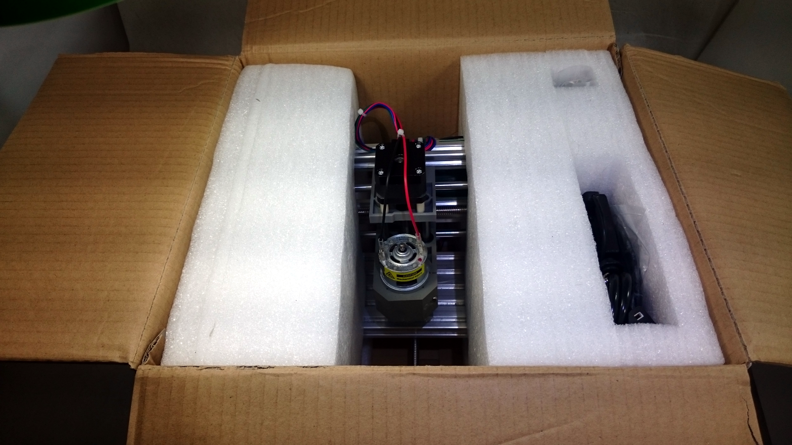
Once home, it was time for the unboxing. I don’t know what I was expecting, but it’s obvious that LinkSprite cares about this product. It was well-packed inside a custom Styrofoam shell and a thick cardboard box. I figure if they’re going to ship it like that, it will be in good shape when I get it even if it’s thrown around a bit in transit and/or by store employees.
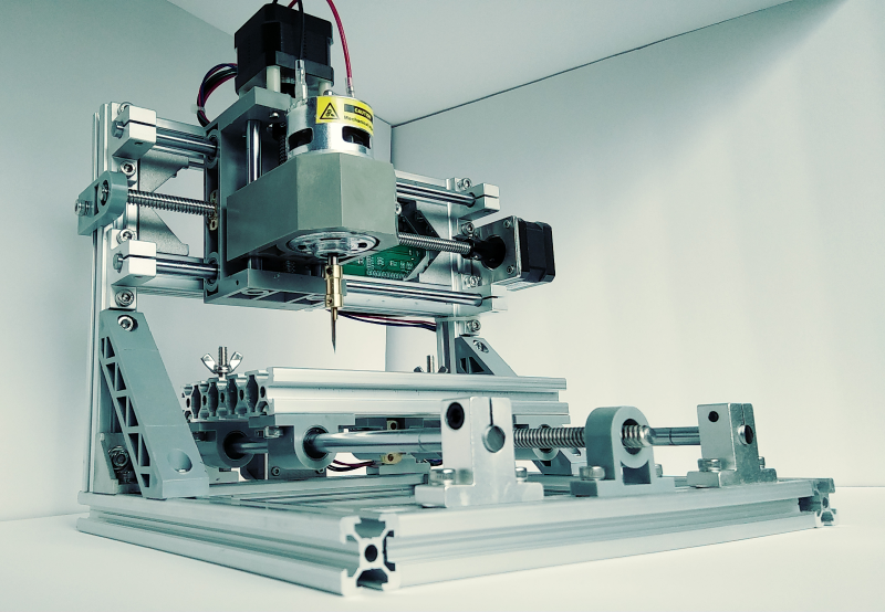
My first impression was that it just looks cool. It’s minimalist and utilitarian, and has a tiny footprint. If I ever wanted to take it somewhere, it would easily fit inside a milk crate. This thing has what it needs and nothing more. The chassis is about 80% extruded aluminium and the rest is basically injection-molded plastic braces, cast aluminium connectors, and a handful of t-slot hardware. Functionally, there are three motors for Cartesian movement along with the requisite rods and rails, a spindle motor for carving, a control board, and some cable ties. Because it’s mostly aluminium, it only weighs 12 pounds.
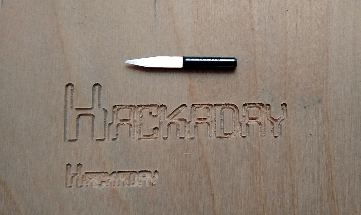
It comes with two 3mm engraving bits, both of which are half-round and pointy and seem to be good for carving acrylic and decent for softer stuff like craft plywood. Since I want to engrave PCBs, I’ll probably buy drill bits for through-hole designs and a couple of flat end mills for different trace widths.
There is No Setup
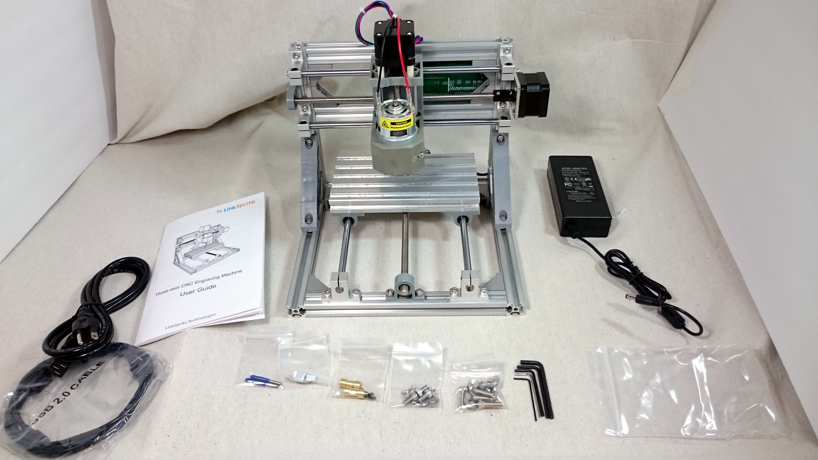
There isn’t much to do once it’s out of the box. Along with the power brick, it comes with a USB mini cable, two chucks, two bits, clamping hardware, and five Allen wrenches. The one I got comes completely assembled. All I had to do was chuck one of the bits and slap the heat sinks on the motor driver chips. There’s a kit version out there too, which looks to be about $50 cheaper and explains all the Allen wrenches. If you get the kit version, here’s a slick build video to go with it.
The coolest/scariest thing is that LinkSprite sells a laser head add-on for $39. I haven’t gone looking for details about laser-safe honeycombed bed alternatives, but that is one of the first things I will secure before trying the pew-pew-pew. That, and a suitable enclosure.
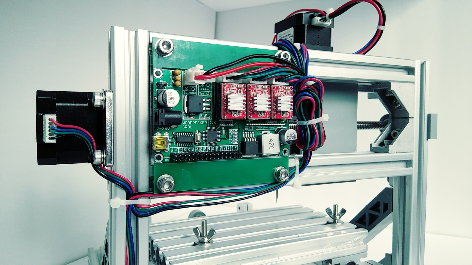
I have only one concern with this machine so far. Maybe it’s just this lone unit, or maybe it’s this dry Midwestern winter, but there’s a spark at the board when I plug the barrel connector in. This has happened almost every time I’ve used it.
Carving a Thing: Design
As far as 3D conceptualization goes, I have the most experience designing with OpenSCAD and using Cura to print on a Lulzbot Mini. If you have experience with 3D printing, then this particular machine should not, in my opinion, present a steep learning curve as far as getting it to do anything at all. Getting it to do exactly what you want, though, that’s going to take some trial and error.

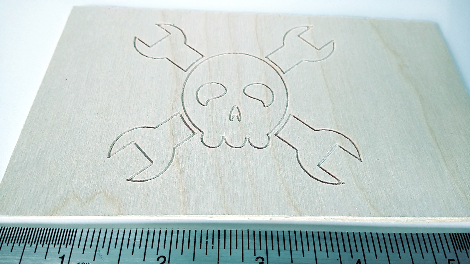
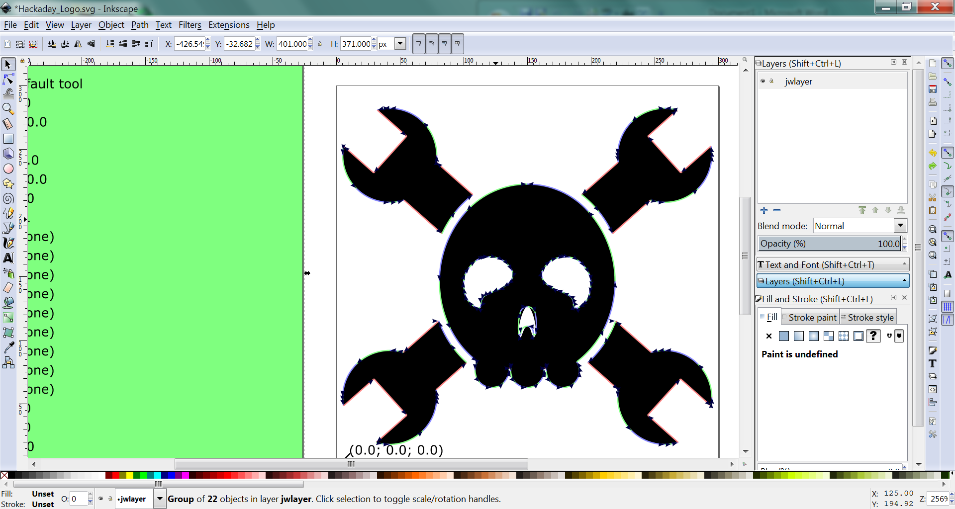
So far with the LinkSprite I’ve used Inkscape to import pictures and create text for carving both 3mm craft plywood and a similarly thick piece of acrylic. I decided to skip “Hello, world!” and went straight for the Jolly Wrencher. The holidays were fast approaching, which was perfect timing for a little show and tell. I made the “Happy Holidays” carving to show the family and because I wanted to see it carve in Edwardian ITC.
In the future I’ll be expanding my horizons by trying different designs and substrates in my ultimate quest to engrave my own PCBs. Software-wise, I already have my eye on FlatCAM when the time comes for that.
Carving a Thing: Getting Ready
The LinkSprite ultimately needs a list of g-code and a specified step depth. Inkscape has native extensions that generate g-code for you and let you set up the bit diameter, feed, and depth step. A tutorial on this process is beyond the scope of this article, but if you’re interested in a future article devoted to that, let me know in the comments.
Inkscape is capable of sending g-code directly to CNC machines, but for now I’ll be sticking with Candle. This is the program the booklet pointed me towards that has since been renamed from ‘grblController’. Candle is like Cura in that it provides a slick interface for manually controlling the XYZ position of the tool head and sending g-code to the machine. The major difference is that Cura also slices. For all I know, Candle may slice, too, but I’ve been using Inkscape for that. To continue the 3D printing analogy, Inkscape also handles setting the step depth, which is the subtractive process’ answer to layer height.
Before homing the tool head it’s time for the most important step: clamping down the work piece. The machine comes with enough t-slot hardware and washers to make four clamps, but for everything I’ve done so far, I’ve used two of these in the back and a pair of large binder clips in the front. In the kit video I linked to above, the guy uses flat corner braces made for fortifying joints. Certain Erector set pieces I have lying around look promising, too.
The LinkSprite doesn’t automatically home the tool head, so this must be done manually with Candle. That’s easy enough, just move the bed in steps to the start point and zero the XY. Then, do the same thing for the tool head and zero the Z in relation to the thickness of the material.
Carving a Thing: Where the Bit Meets the Substrate
Once the g-code is ready, the work piece is clamped, and the tool head is at (0,0,0), it’s time to carve. This is as easy as starting the spindle motor and hitting send in Candle.
Candle shows, among other things, a carve time estimate. Everything I’ve done has taken a little bit longer than anticipated. The estimate for Happy Holidays was 34:20, but it really took 39:17. C’est la vie.
My favorite thing about Candle is that it lets you follow along visually—there’s a wire-frame 3D representation of the tool head superimposed over the model of whatever design is being engraved. While it’s engraving, the virtual tool head on the screen traces every step of the actual tool head in real-time and you can zoom way in if you want and watch it do each layer.
Lessons Learned So Far
Clamp the work piece well. Yes, it’s a tiny machine, but it’s still applying pressure with a sharp tool at many thousands of RPM. If a poorly secured substrate suddenly goes spinning across the room, the bit is likely to hit the bed and break off and do unimaginable damage. (This is not so much a learned lesson as it is a preconceived precaution.)
Don’t forget to zero everything. Unlike a 3D-printer and some other hobby CNC mills, this machine doesn’t do any homing by itself. It must be done manually through the grbl controller.
Start the spindle first. It’s easy to miss this warning in the booklet and assume that the spindle will start spinning as part of the carving process. It doesn’t. You have to start the spindle motor and then send the g-code, or else the bit will stab and drag and probably break.
Buy more bits ASAP. Especially if you dull one by not starting the spindle motor first. You’re going to need more eventually, anyway.
Check the design dimensions. Will that Jolly Wrencher be 5cm across or 5mm? Likewise, if you’re planning to engrave words, check your font size so that it doesn’t end up really, really small.
This is a Good Robot
Based on my experience so far, I’m really happy with this purchase. This would be a great buy even at twice the price. It’s a good, entry-level machine that’s relatively easy to use, more so if you have experience with 3D design and printing. If you want to spend a little and learn a lot, this machine can be your cheap education in the subtractive arts.
What’s Next?
My ultimate goal is to engrave my own PCBs. I’ll be studying the guide that [Adil Malik’s] PCB milling guide which we published a few weeks ago before giving this a try for myself. I’d also like to try milling a bunch of materials, including some non-obvious ones just to see what happens. Here is the shortlist: corrugated cardboard, a glued stack of chipboard (cereal box cardboard), a linoleum carving block, and one of those flat little hotel room soaps. Will you join me?


nice, just received this kit yesterday… still haven’t build it..
I got one similar to this about a year ago from bangood/gearbest? for about 140. no axis zeroing and the bed was my biggest complaint. you could mod it easy with a z touch probe to set z height. I tossed it in the building somewhere after a couple weeks and got a 3d printer which has held my attention ever since.
Fitting limit switches took me about an hour. All the pins are there on the controller.
I never found an easy way to mount them and it headed to the building before I could bother.
Could you post a few pictures of where and how you mounted those pictures?
Also a dump of default settings $$. my firmware got corrupt and I didn’t have a copy saved.
Might be a weird place to ask this, but are you interested in selling your unit? I want to redesign a frame for this unit which will be open sourced on hackaday.io when completed.
Hi Scott
Any chance you could upload photo instructions of how to connect the touch plate and the correct pin to use? Cheers
the spark is probably that cap right next to the barrel connector gobbling up all the charge it can from the many amp DC supply. there should maybe be a high current choke between the connector and the cap?
A choke large enough to limit the inrush current will cause other problems.
I get this on my laptops, have for a long time. So I plug the charger into the laptop, then plug the charger into the wall. Puts the spark where it is less likely to cause damage, and less likely to cause damage to parts harder to replace.
This is presumably why Apple laptops (and I’m sure other good brands) don’t supply power from the PSU until the laptop has talked to the PSU and told it it’s connected properly.
Laptops have the luxury of having the load isolated from the supply, because they have power management chips to switch the power to the charging circuit and the power to the computer in an organized way. To get limited inrush current on something simple like a microcontroller board, you would need to add similar circuitry. In particular, you’d have to charge the offending capacitor through a resistance until it reached a certain voltage before switching the main power switching transistor on. Which I guess isn’t that difficult after all – power-on reset chips have been around for a couple of decades to handle that sort of thing. And while you’re at it, you can also throw in an emergency stop switch, which really ought to be implemented on any machine that moves things.
I was alarmed by the magnitude of the spark when I first plugged mine in. And the next time, and pretty much every time. My solution was to leave the power supply plugged into the control board and just unplug the AC cord. That’s much easier to replace.
This also serves as my “emergency stop switch”. I quickly rammed the engraving bit into the baseplate and then one of the hold-down clamps within an hour of finishing the build; after that, I moved the power supply so its cord is always accessible. Interestingly, the controller board is actually powered from USB; the 24 V input is used only for motor power.
Nice review.
+1
Once again a ‘Jeez, why didn’t I think of writing that up’ from HaD!
Thank you!
One thing to be VERY careful with this CNC is that it can kill your PC if you plug in the USB before plugging in the CNC power supply. This is because the power supply jack makes center pin connection before the ground makes connection and there is a lot of capacitance on the CNC PCB. When you plug in the power jack and already have your USB cable plugged in then the power supply ground return path is momentarily through your PC. The inrush current to charge the on board capacitors effectively causes a large current through the USB. On m,y PC it killed my gaming motherboard.
The other issue I have is that the spindle causes a TON of noise on both the power supply, and hence back to the CNC micro controller and USB, so much so that it keeps loosing USB connectivity. This causes the job to terminate. I ‘fixed’ this issue by providing a different power supply for the spindle and manually turning it on and off.
I still think it is worth the $200, but it is not really for a complete beginner.
You might also have fun trying ‘cnc.js’ for your control software. It’s hardware agnostic, unlike Candle(That I love, but doesn’t support TinyG) It works surprisingly well.
JavaScript, really? How about “No”.
Was also my first thought. But after taking a closer look, this is propably one of the best (free) Controllers for GRBL out there. No g-code creatio, but therefor a great interface und a good connection serial connection with the controller board.
Why not?
Just be glad it’s not Flash.
There’s also UGS, or Universal Gcode Sender, which is a Java program. I’ve tried both Candle and UGS, and both work, but each has its own quirks.
And by the way, UGS WILL send motor start and stop codes, so you don’t have to manually start the spindle motor. The simplest workflow I’ve found is HeeksCNC, with which you can do 3D drawings from scratch or import them from anything that generates dxf files, and then generate toolpaths. It doesn’t send the Gcode directly to the printer, though, so it still takes either UGS or Candle to take care of that.
I found a similar unit on sale and picked it up to try. The simple things I used it for worked well, but while moving it around I knocked the power supply and connected cables off the desk and pulled the USB connector off the circuit board. I ended up getting a replacement board on ebay which brought my price up to about what it would have normally been. I 3D printed some pieces to hold the power supply and a cover for the circuit board. Also added a USB to panel cable adapter to prevent a repeat. Because you are changing tooling quite often with different lengths you do not usually use endstops like a 3d Printer. There is provision in the software to use Z probe electrodes to set the Z axis zero using just a couple wires from pins on the control board. I have documented some of these mods and a couple of the circuit boards I made with this CNC machine on my blog at https://kv4qb.blogspot.com/2017/11/cnc-engraver-update.html After the mods I have been very happy with most of the results for many PCBs I plan on making. But for ones with smaller SMD parts or double sided boards, I will probably just use it to drill any holes, and etch the board.
Your work piece holders look like they rock. Looking forward to printing up a set.
+1 Those are awesome.
I was looking at these just before Christmas on the usual Chinese sources, but they were too small (like 160 x 100 mm) for what I wanted to do. I have a big project I’m working on that requires thin plywood parts up to a foot wide and 5 feet long. Fortunately I found that there were also other sizes available, and I got the largest one I could find, which could do 180 mm x 300 mm. The 300 mm is the X axis, and while the Y axis is only 180 mm, by breaking the designs into 180 mm sections the Y axis is limited only by how much space you have available in front of and behind the machine.
By shopping around a little, I found one that used an ER11 collet holder instead of the cheap brass coupler, at no extra cost. The main benefit of this is that for the price of a cheap set of ER11 collets I can fit any tool from about 1 mm to 7 mm, instead of just 1/8″ Dremel cutters.
Mine was in kit form, which was a blast. The Z-axis unit was preassembled (its main components are the same 3D printed ABS as seen in the picture in this article), but everything else was literally pre-cut lengths of 2020 extrusion, and nuts and bolts. The bigger adventure was getting all of the software downloaded and installed and running – that which came with the kit seemed pretty useless. That was two weeks ago; since then I’ve played with QCad, LibreCAD, and FreeCAD for drawing, HeeksCNC and the FreeCad “Path” workbench for toolpath generation, and both Candle and UGS for sending the files to the machine.
Just getting started with my CNC like this one featured. One very annoying feature is the stepper motor couplers fix to the threaded rod using two grub screws which keep coming undone. It would be all too easy to strip the thread by over tightening the grub screw with the supplied (truly cheap and nasty allen keys).
Eventually I had to remove the threaded rods and file flat surfaces on the ends. Then tightness of the grub screws became less of an issue. I also put a couple of turns of tape around the coupler so that I didn’t need to hunt all over the floor in case they fell out – which they did more than once.
Loctite 242 (blue). Remove screw, put in a drop or two, reinsert screw and snug. It will keep the screw tight, and also tie the shaft to the coupler. With a little force, it can all come apart if needed. No heat needed in general.
I had the same problem, and Loctite “blue” is probably the correct solution. My solution, because this was at 2 a.m., was just a bit of contact cement at an edge of each of the grub screws. This machine makes a LOT of vibration. I’m using one of the foam pieces that the parts were packed in as a pad to keep the whole table from being a sound board.
Still, there are other screws that keep coming loose, so I guess I’ll have to buy a bottle of blue.
I replaced all those connectors with three layers of heatshrink and zipties. Far more functional.
8020 tubing is about as precise as a sledehammer and an un-damped aluminum frame as rigid as an overcooked noodle. The ‘spindle’ probably has more run-out than the New Orleans Saint’s safety and the Z-Axis carriage is susceptible to environmental changes. But what do you expect for $200. Two hundred freaking dollars for a ready-to-run CNC machine. Sure it will never do metalwork, but what it can do for that price is pretty amazing.
I just received a $2300 quote for a single 20″ long replacement ballscrew for my Benchman XT. Apparently custom P5 ballscrew assemblies aren’t cheap. Needless to say I’ll be looking at rebuild options instead.
You might want to consider ordering a ballscrew from China / Taiwan / Ali / Ebay. Just as everywhere Chinese quality is what you pay for.
Tbi seems to make quite nice ballscrews. C5 Ground ballscrews with double nut start arout USD400.
C3 cost around USD1000.
Thanks, I appreciate it. I’ve been looking at TBI already, one of the outfits that advertise C5 or better in a stock rolled 1605 ballscrew. (Gten is another.) An amazon seller claims to sell genuine TBI C3 at suspiciously low pricing. The challenge is that the original ballnut is a rectangular block 40mm W x 35mm L x 30mm H, bolted from the bottom (into the 40×35 face), and I’d need to do extra to mount a TBI nut. I’m going to evaluate the $10 reball fix before I go that route.
https://www.amazon.com/TBI-MOTION-Screw-665mm-DFU1605/dp/B01I4VP2NG
Your spindle comment almost made me spit up the water I was drinking…
Can you explain your critique further? As someone who doesn’t know much about CNC machines, why 8020 profile is bad? How do you make an aluminum frame damped? What can you do to solve the spindle and z-carriage problems?
8020 isn’t itself bad, but this just isn’t an ideal application for it. 8020 is extruded. Extrusions bend and twist during manufacturing – I believe that 8020 is specified to be straight within 0.012″ over 12″. If you need flat metal then you need machined metal. 8020 isn’t milled or ground – and isn’t flat. For typical 8020 applications 0.012″/12″ is just fine, but for machine tooling that is abysmal.
If those Y-rail mounts are 8″ apart then that means that one of the Y-rails could be 0.008″ higher than the other. For example, if the left rail was 0.008″ higher than the other, then the spindle would be 0.008″ closer to the work on that side, and parts would thus be cut 0.008″ lower there. If you took some 0.25″ thick flat parallel-sided stock and tried to take 0.1″ off the top then you not end up with a 0.15″ parallel-sided part, but a tapered part when the top surface sloped from left to right. This is assuming that the rest of the Y and Z components are in tram, but, they likely have similar issues of their own.
For wood and most plastics that 0.008″ isn’t likely to be critical. Both materials are subject to moisture absorption which causes swelling, and designers using those materials should design using tolerances to allow for that absorption. For example, when installing a hardwood floor in a 120″ long room you leave a 0.5″ expansion gap at each end. That gap is then covered by a 0.625″ trim, so your cut needs to be within 0.125″ to be covered whilst maintaining that gap. The critical thing is this – the design of the wood floor includes large tolerances to allow for semi-skilled people to install floors that look good and that won’t buckle in a humid summer.
+0 / -1/8″ (or +/- 1/16″) is a typical tolerance for non-finish carpentry. +0 / -1/32″ (+/- 1/64″) is a tight tolerance for wood, yet still 4 times larger than that 0.008″ tram error. When cutting wood, 0.008″ is fantastic.
For metal though, that 0.008″ error is a problem. If you tried to press a bearing into a hole that was 0.008″
too small then you’d destroy the bearing before successfully installing it. If you installed a bearing into a hole that was 0.008″ too large then the bearing would be sloppy, leading to poor shaft alignment. That 0.008″ error matters. A lot.
Different plastics have a large range of differing characteristics so are difficult to generalize. You might be able to press into marginally undersized holes on softer plastics, but not on harder brittle plastics. For engraved plastic plates, you likely wouldn’t see that 0.008″ error in an engraving cut 0.125″ deep. (Same is true for most engraved wood, unless you were engraving laminates and that error took you through a layer at one end only). HDPE is a readily machinable plastic that holds good tolerances. You might choose to build a gearbox housing from it, and that 0.008″ might matter in that situation.
Dampening requires absorbing vibration. That typically requires mass. You could improve this machine by bolting it to something heavy such as a granite counter-top offcut (which are usually pretty darn flat btw), or embedding it into concrete (paint with an epoxy paint first to prevent corrosion). That wouldn’t help you with the upper axis though, and it would be easy to spend more time and money on this machine than the results are worth.
The Z carriage is plastic and subject to moisture absorption and swelling. Replacing with aluminum would help improve tolerances there, but then you might have weight issues requiring more heavy-duty steppers and/or ballscrews.
The spindle appears to be a cheap electric motor. It’s likely that its bearings cannot handle axial loads, nor excessive radial loads, neither of which are usually seen in gearbox applications. In addition, a few thou runout isn’t critical in cheap gearbox or belt drive mechanisms. Cheap motor, cheap bearings. You at least need something that was designed to handle those type of loads – trim routers are a popular budget choice. Air-powered grinders (loud!) are another possibility. Again, weight is likely to become an issue here. (FYI, spindles designed for CNC often use 4-5 bearings that cost $400+ each.)
The reality is that by the time you improve this machine to the point where it cuts aluminum well, you’d be better off just buying one designed that way to begin with.
This. Yes. Epic response. Where are people like this dude(?) when the internet really needs them??! Go run for president or something – hot damn if the planet doesn’t need sense and reason like this right now.
Dion beat me to it, but this has got to be one of the best responses I’ve seen on Hackaday. Thanks ID!
Yup, this is an incredibly helpful and informative reply.
Now make him write articles!
“8020 isn’t itself bad, but this just isn’t an ideal application for it.”
I disagree. What are you imagining the application is? To me, the application is making a hobbyist-affordable machine that can do low-precision working of relatively soft materials into imagined shapes, and versatile aluminum extrusions are perfect for it. The fact that you can identify worst-case examples of bad applications for a machine like this does not in any way imply that there is no good application.
Machines like this, using materials like this, exist because they have risen to the top among many even poorer solutions to a recognized need, the need for po’ folk to have fun making things they think up, relatively efficiently, without requiring years of skills training.
Would you have said (or DID you say) when the first FDM printers came out (or even TODAY’s FDM printers), that they are a terrible application of the materials used, because after all, there are already 3D printers that can do far better resolution and accuracy, never mind that they cost 50 times as much? If you’re not in the target market, I guess you may not understand.
Don’t get me wrong; I really DO understand your position. In my work, I have a $half-million TV studio at my disposal, and when I do that work, I expect the equipment to perform up to the highest standards, to produce results that conform to those standards. But that doesn’t mean that I look down on YouTube videos made with people’s cheap cell phones or old camcorders. It’s not about the perfection; it’s about the story. Which is why I still use my $300 camcorder or my $50 cell phone when I’m not at work. You know what they say – the best tool for the job is the one you have.
So if somebody wants to do a professional job on their living room floor, and blindly trusts that a $200 machine will make each tile exactly the size he asked for, yes, he’s going to be disappointed. The first time. Then he’s going to learn to double-check and adjust.
Aside from all of that, and maybe I should have opened with this, I have to point out an error in your reasoning. You state that the twist in an extrusion can result in the worst-case error in the machine as a whole. But that assumes that the builder will just blindly screw all of the pieces together and call it good. Even with perfect extrusions this wouldn’t be acceptable, because there is considerable play in the corner fasteners that would introduce far worse errors. This machine can be made as accurately as the builder wants. Note that the accuracy of the machine is determined by the accuracy of the parallel rails. And note that the slide rails are attached to those inappropriate 2020 extrusions using clamp blocks. If somebody wants this machine to be accurate, that twist can be countered by adjusting the corner blocks as necessary to make the rails parallel. Which isn’t that hard to do. I know because I just DID that. Nothing depends on the straightness of the extrusions, so the materials are not the limiting factor. Now, if the rails weren’t straight, that might be a different story.
But whatever. Even if you make something on a six-figure machining center, if you declare the finished part to be finished without measuring it, you’re not a machinist.
Obviously as an owner you have more experience in this machine than I do. Maybe my characterization was a little harsh in that for its intended application (wood and plastic) it does the job. It was clear in that analysis that for cutting wood or plastic being able to hold 0.008″ precision was great, and my previous post in the thread (which you must have missed) concluded, “Two hundred freaking dollars for a ready-to-run CNC machine. Sure it will never do metalwork, but what it can do for that price is pretty amazing.” The later analysis was made considering CNC machines more generally, intended to help a novice understand why this machine (and similar) is limited in its applications, in response to a direct question.
As you indeed observed, the 8020 itself isn’t the only challenge with dimensional accuracy in this machine. Aside from the play in the corner fasteners (typical for 8020 / tslot type construction) the material of those fasteners will react differently to thermal and moisture changes, so you can expect some unpredictable dimensional changes with the seasons. Sure you could try to square the machine whenever you needed the most accurate parts, but that will still have limitations, and doesn’t sound like fun. Even if you align the corners well, the rail itself can still have 0.25 degrees of twist across 12″ of length, and 0.004″ error in flatness across its 1″ width, both of which create the same kind of error as the previous analysis, and neither of which can be corrected. In the worst case all of those errors could sum. Napkin math suggests 0.0014″ error possible from a 0.16 degree twist across 8″, not massive.
Those round linear rails are possibly stiffer than the extrusions they are mounted to. They can be somewhat forgiving of alignment errors, especially those perpendicular to the plane that a parallel pair form (i.e. alignment errors in the Z direction for the Y rails, or the Y direction for the X and Z rails) because the carriages can rotate on the shaft. In this application that is actually a good thing – with a rectangular linear rail system those same alignment errors could cause the axis to bind and the stepper motor driving it to miss steps which would lead to part dimensional errors of much much worse than 0.008″, and basically make the machine unusable. Rectangular rail requires flat, aligned and stiff mounting surfaces – the higher the precision of the linear rail system, the more precise that mounting needs to be to avoid binding.
In machine tool terms, those rails are still considered floppy – they are supposed to be mounted to something flat that is much stiffer than they are and provides the necessary alignment to keep them straight. That is true of linear rails generally, a design principle that isn’t well observed in this machine. We don’t know how straight they are as mounted. Note also that because of the slop inherent in 8020 channel nuts, you can have those rails parallel, aligned in the perpendicular direction just discussed, but out of alignment in the direction of the 8020 they are mounted to with the clamping blocks twisted on the rail. The end result would be movement out of square to the commanded axis – Y commands would also move the table a little in the X direction, X commands would move the gantry a little in Z, Z commands would move the spindle a little in X. Square parts become trapezoid, round parts become elliptical.
Another observation – we can infer from the construction and cost that the ballscrews are limited in their lead accuracy, and almost certainly will have some backlash. You should be able to compensate out much of the backlash in software. The lead accuracy is an interesting question – a manufacturer’s cheapest grade rolled ballscrew can end up with the same lead accuracy as their best grade because they typically only use one die and machine per size. They inspect and guaranty the lead accuracy to a higher standard for the higher grades, and that certification is what costs the money. A budget manufacturer might not be able to hit those higher standards to begin with. The good news is that even the cheap ballscrews are better than the average acme thread or leadscrew in most applications.
One final point – we’ve been referring to the extrusions as 8020 and I’ve been using their specifications in my analyses. I’m pretty sure looking at the photos though that it is a clone and not 80/20 Inc. extrusion. That could have all sorts of ramifications on strength, stiffness and accuracy. (Not necessarily bad, but if I were a betting man…)
Given all of this I suspect that you’d be hard pressed and doing very well to keep errors in this machine below 0.010″ in all axis simultaneously, so I disagree with your claim that ,”This machine can be made as accurately as the builder wants.”, unless you can be absolutely sure that is as accurate as any builder ever wants. :)
But again I’ve gone into critical analysis, and I don’t want to take away from the reality that compared to what a hobbyist could do with a few hundred bucks just 10 years ago, this machine, like other similar machines, can kick ass. Yes, even using slotted aluminum extrusion. I have spent enough time in my life cutting wood or plastic with hacksaws, circular saws. jigsaws, bandsaws, drills and rotary tools with much less accuracy than machines of this ilk can achieve.
Regarding the screw backlash, it won’t do miracles, but these CNC uses two nuts with a spring to try to limit backlash…
Thanks! This will greatly helpful.
It’s a juicier response than I had expected, but I’m not going to complain about extra nibbles of info.
There are jobs for which you need a $100,000+ machine, and there are jobs for which a $200 machine is the right tool. And if your YouTube channel happens to be called “myfordboy”, you’ll take an under-$200 machine and put that much more into it in the form of replacing plastic parts with metal and upgrading the motor to a 400-watt unit, and then you CAN machine some metals with it.
I know most machinists scoff at any “machine” made with aluminum, and I won’t bother to try to convince any of them that these can be useful.
I bought one about a year ago. I really like it after returning the first one I got to MicroCenter because the controller died. Ther replacement was the kit version, which goes together nicely. Aligning the X axis was a bit tricky, bit a dial indicator took care of it.
I cut a stack of 1/4″ masonite as wasteboard, drilled holes for alignment pins in each of the 4 corners of the board and put some 1/4-20 nuts on the bed. Nice, repeatable results.
As I mentioned in an earlier post, limit switches took about an hour for very simple ones. All the pins are already available for those and the Z axis probe.
By far, the best addition was, however, bolting the Pi Zero W onto it so it is now wireless. No muss, no fuss. Using chillipeppr I can drop eagle PCB drawings onto the workspace, zero out the bed, run an auto-level, and off it goes.
Picture of the Pi Zero and limit switches here:
http://www.correctivephrenology.com/blog/?p=98
I’d suggest a switched outlet, power strip etc for the power supply. Let’s the sparking stay where it’s supposed to be.
“I’m a bit leery of the chemicals used in the PCB etching process, so the idea of engraving them instead was especially tempting”
I am having trouble understanding this concern given that the fiberglass dust coming from the milling process is potentially much more harmful than the ‘chemicals’ used in etching, like vinegar: https://lowpowerlab.com/2012/12/15/cheap-pcb-etching-with-vinegar/
Even ferric chloride and other industrial etchants are pretty benign if handled safely. I wouldn’t mill fiberglass PCBs indoors without HEPA-filtered vacuum dust extraction during the milling process. (Many household vacuum cleaners have a HEPA filter option.) But even just drilling creates dust, so you would likely need this protection in place for etched boards as well.
Yes, I have been eliminating through hole components as much as I can for that reason. Luckily you can find all kinds of SMD versions for what used to be through hole only, like connectors and pin headers. One can even manually trim the regular 0.1 pin headers to be used as SMD components in a pinch. We just don’t have a good solution for plated via’s.
What I wonder is whether I can use the laser to remove paint or such think from copper clad board to etch it, to avoid toner transfer or photographic process…
Ferric chloride is easy to neutralize with washing or baking soda. It should never be disposed of where it could enter the ecosystem because the copper is toxic to aquatic life. Consider this though: its primary use is a coagulant – 88% of FeCl is used in water treatment, either to remove impurities from reservoir water before piping it to your house, to remove detritus from wastewater after it left your house, or in industrial wastewater treatment. The biggest risk of flushing small quantities down your sink is that it can stain and etch metals and ceramics. I have a Radio Shack bottle somewhere that has instructions to dispose of it by flushing down the toilet.
It’s better to neutralize it with soda, label it and take it to your local hazmat collection point though.
For milling PCBs, I normally use Fritzing and FlatCAM. Fritzing can export Gerber files for the traces and holes. FlatCAM can import these Gerber files directly and output the Gcode.
$200? It’s 269 now.
snooze, ya lose!
B^)
Bought a kit version from ali for 230$, including the 50$ dhl shipping and a 2.5W laser
just got a 3018 with an er11 chuck and 10 bits on amazon the other day for $240, should show up later today, gonna start watching the Chinese sites for a decent spindle and laser to go on sale now.
Anyone know a cheapish source for the drill head mount similar to kv4qb’s? I am building my own Pcb mill now, and have been thinking I’d use a servo to lift the spindle (a lightweight dremel), but perhaps it would be skittish in the cutting position compared to a stepper… My frame was going to mdf, but now I am wandering on that too. I need to produce soic8 footprints reliably. Would welcome any advice.
*wondering
I can 3d print parts…
check thingiverse, lots of mounts for the root cnc or cyclone pcb factory should be adaptable to what you are making.
I bought two of these about a year ago when Microcenter had them for about $200 (one was for a friend). Mine sparks too and I haven’t done as much as I thought I would both because it generates lots of sawdust (I need to move it) and I just haven’t had the call for it. Definitely buy new bits. I’ve also thought about printing an adapter to take a Dremel flex shaft which is probably no worse than the included spindle.
I’ve had good luck using Easel although Chilipeppr has worked too.
The CNC/PCB mill I built before I got the LinkSprite uses a pneumatic die grinder. Runout is great but it is loud as fsck, even with the compressor in the garage 150 ft away. I pretty much cannot use it when $SPOUSE is in the house.
Bought a 2417 variant last month for a few bucks more with an ER11 collet… those brass couplers that ship with these kinds of kits have horrible run-out, the Er11 was a good investment (added $10-15 over the same kit without it). I just documented my PCB workflow in the amazon review here: https://www.amazon.com/gp/customer-reviews/R19YAGWABEWWCY/
Its also worth upgrading the hold-downs, I came up with a cheap and simple hack for that: https://images-na.ssl-images-amazon.com/images/I/61axOxJDUZL._SL1600_.jpg
Nice review. Some small corrections/suggestions:
1) grblControl is now called Candle (they’re the same project). The current version, 1.1, requires grbl 1.1 on the controller, but Candle 1.0 and earlier work with grbl 0.9.
2) Candle is multiplatform open source, and there is a pre-built dmg for Mac available. This is the one I tried first, so I know it works on the Mac.
3) Universal Gcode Sender (UGS) will also handle the task of directly controlling the machine, and sending files to it. This is also multiplatform through being written in Java; I’ve used it on Mac, Linux, and Windows. There is some trickiness to using it in Mac: you have to make sure that any users who use the machine belong to the “dialout” group in order to recognize the serial port. I don’t know if this same restriction applies to Candle, since by the time I tried Candle I already had the group set up.
I also bought a similar one 6 months ago. Adding end-stop switches was quick and easy, so as adding z probing capabilities (z-probing is absolutely needed for autoleveling before PCB carving): just connect wires to the connector on the board and enable homing in Grbl. Btw, I successfully installed the Arduino bootloader on the board and upgraded the Grbl firmware to the latest version (1.1f). As g-code sender I’m happy with bCNC (works also on MAC OS X) which greatly supports auto-leveling. I’m currently working on a dust collection shoe and meditating about attaching an endoscope camera to the z-axis…
I love my machine. In fact, I added hardware limit switches, and bed leveling, built it into a fully enclosed cabinet with lighting and dust extraction. You can see it by googling GhostPepperCnc. I sell them for anyone who is interested.
So basically you buy these Chinese mills, add an enclosure and resell them?
https://www.kickstarter.com/projects/464299954/ghost-pepper-desktop-cnc
179 right now at STL microcenter
Check out bCNC as a software controller.. it also features the visual display of the current job, but also includes an autoleveller, and a g-code editor :)
I just use Chilipeppr with my ShapeOko 2
I checked out chilipepper, but the fact you need to be online is a tad annoying.. I also tried UGSplatform, GRBLcontrol, Candle, UniversalGcodeSender, OpenCNCPilot & CNCjs. OpenCNCPilot looks promising as does CNCjs, unfortunately when I open CNCjs, the spindle starts and does not stop :/ But I like bCNC for the features it has. GCode editor (pretty awesome), Autoleveller (works beautifully), I can import DXF’s directly and it generated gCode for it, Macros etc etc..
I like using ChiliPeppr. bCNC looks like it is from the 80’s. UGS seems old now too. ChiliPeppr has lots of features and the fact that it’s online has never been a problem for me.
I bought one about one year ago. Still did not make it run properly and it sits in a box. It was a kit. Had trouble aligning the stuff and I am having the same problem @Tony says with the coupling.
I sort of managed to make a bit of good PCB milling…but….
For PCBs, considering how long it takes, how difficult it is to get a proper carve, the dust and noise, i still think this is better for just drilling the holes and then toner transfer / UV.
I have a similar one that is bigger (3018 variant) which also uses the same controller board. I think you should clarify in the article that it is the software you are using to generate gcode which is not starting the spindle. When I generate gcode then it always starts my spindle before carving.
Could you cut 3 mm thick wood pieces with this machine? Or is it only for engraving?
You could probably cut 3mm wood, with the right bit and slow passes. Just a guess, I don’t have one. I do have a laser engraver; with the right laser it will cut 3mm material.
Note that the reviewed machine is not quite a 3-D CNC machine, since it only has 30mm of Z-axis range. If I had a bigger toy budget this winter, I’d consider getting one, or similar with more Z-axis range.
Thank you for your answer. The problem is that a laser able to cut 3mm material is expensive and dangerous, and it leaves burnt edges when cutting wood… And I guess that the laser they sell with the machine would not be powerful enough (500 mW).
My engraver currently has the 500 mW laser, and no, it wouldn’t cut 3mm anything. Butter, maybe. But you can install a higher power laser that could cut such materials for under US$400. And yes, scorched edges.
On ali express, for these machines, you generally have the options:
– without laser
– with 500mW laser
– with 2500mW laser
– with 5500mW laser
It won’t become a laser cutter easily, but there is video of wood cutting with a laser and multiple passes, yes burnt edge, and using 5500mW seems possible on some wood:
https://www.youtube.com/watch?v=DdEfouv90Lc
Thanks. I’m too scared of using such powerful laser… And I wouldn’t trust the glasses they sell with it… Anyone actually tried wood cutting with the CNC head?
lol, I bought kit with the 2.5W one… and I definitely won’t trust the goggle, I was thinking more about having it totally enclosed and never use it open… think interlock… the only major issue I foresee is about having to adjust focus…
elwing: the key to laser safety with these machines is the focusability. Once you get any appreciable distance from the laser, the beam diverges enough for its intensity to be greatly reduced, to the point where the goggles are effective.
Can’t wait for you to engrave PCBs on it.
YouTube search on CNC 2418 PCB:
https://www.youtube.com/results?search_query=CNC+2418+pcb
LINKSPRITE MINI CNC aka CNC 2418 on eBay and Amazon.
Anyone have a similarly priced CNC 2417?
Anyone here looked at LaserWeb software to control the CNC? I got one about 6 months ago and use Inkscape and LaserWeb (https://github.com/LaserWeb/LaserWeb4) for my purposes. I was wondering how that compared to the other software mentioned here.
LaserWeb4 is pretty good. I use that, and yes they have. or will soon add CNC-type functionality with control over the Z AXIS.
I have this machine, and the 2 main issues/annoyances are:
1. The method of fixing the tool to the spindle
2. The leadscrews coupling pulling off the stepper motor shaft (although I assume this can be mitigated by a slower feed rate)
Great review – I like your style – strong & purposeful..
I suspect my Department of Domestic Harmony would not approve of this purchase.
Great review. Thanks.
I recommend giving the engraving bit a try on PCBs. I’ve been using 15 and 20 degree bits on the othermill and find it creates cleaner traces than a flat end mill (also cheaper) – adjust the cutting depth until you just break through the copper for best resolution. FR1 dust is supposed to be less toxic, but doesn’t feel super healthy.
I already did a Pcb with the slightly bigger version (2418). I’m pretty impressed with the result. All 0603 and Lga 8 with 1.25mm pitch and dfn6 with 1mm pitch:
https://drive.google.com/file/d/1ovoh6y5xee7J_mZji7zBXSvo55QKvZHb/view?usp=drivesdk
Based on the responses to this article, I’d say we’ve come to a point where every hacker will soon have (or at least want to have) a CNC “engraver” right next to his 3D printer. I did it the other way around – I’ve had my “3018” engraver for a couple of weeks, and I just ordered my Anet A6 3D printer from GearBest last night.
Somebody please stop me now: I’ve been thinking about the possibility of designing 3D printed parts slightly oversize, then CNC’ng them to precise dimensions, which maybe will give a nicer surface finish…
And THEN, somewhere down that rabbit hole is using this to make models from which aluminum castings can be made, which MAYBE can have critical surfaces finished by the engraver, a’la myfordboy (http://myfordboy.blogspot.co.uk/p/banggood-des.html).
So as I am assembling my 3018 I notice my “woodpecker 2.8” board is different then Kristina’s 2.6, it has a UART at the bottom of the board and seems to be missing the reset button, after a bit of searching I still haven’t been able to find much info about the woodpecker boards, are they more of a gongkia then opensource? Anybody know of a good source of info on these boards?
I don’t know about the Woodpecker board specifically, but this is a clone of the RAMPS 1.4 board, which is an open source Arduino shield, so the technical details like which signals are on what pins should be the same. Full information including schematics available at http://reprap.org/wiki/RAMPS_1.4.
Its actually closer to the cnc shield by protoneeer that is copied all over the Chinese market place, but there is a Chinese cnc manufacturer that sells a line named woodpecker so maybe this is from that company in a round about way.
im trying to convert this into a 3d icing extruder , using dr d flos syringe pump.
very similar to his 3d food printer, but i dont intend to use a 4th stepper motor wired to the woodpecker pcb to control the syringe dispense pump.
any suggestions for what changes could/would be made to gbrl to accept some form of 3rd party commands?
zero CNC experience, full time programmer however.
– I have a complete working syringe pump based off of Dr D flows syringe pump
– I have already bought this machine.
Now to combine the two.. any help would be greatly appreciated.
matt: I was thinking of trying to convert a CNC engraver to handle 3D printing as well, mainly by extending the z axis and upgrading the controller to something that can handle more stepper motors (such as a RAMPS 1.4 clone made for 3D printers). It looked like I could do this for about $50 to start, including a complete hot end and the controller board. But what really convinced me not to do this was the maximum speed that the tool head can be moved. All three axes use single-spiral lead screws with 2 mm/rev pitch. These give you lots and lots of resolution, at the expense of speed. Like maximum around 800 mm/minute, or 13 mm/sec.
3D printers, on the other hand, are built for speed, getting up to 100 mm/sec, using belts or multi-spiral lead screws for greater movement per revolution.
Still, if speed isn’t an issue for you, there are other challenges. Grbl is written for old-school Arduinos using an Atmel ATmega328, such as the Woodpecker board, and when Grbl went from version 0.8 to 1.1, it grew enough that they had to use some of the boot code area. So there’s not a lot of program memory to spare for add-ons.
I hate to say it, but it might be more practical to modify a Prusa-style 3D printer for this task. First, the X and Y movements are on the order of 20 times faster, and then there is already a stepper output set up for driving an extruder, and uses an ATmega2560 with a bunch more program memory available. Also note that CNC engravers have limited Z range, like maybe 40 mm for the type described in the article. Which would be fine for decorating cookies, but not so great for cakes.
Still, since you have what you have, you still might want to look at just replacing the Woodpecker board with a 3D printer controller, so you’ve got the extra stepper outputs and programming space. These are available for $30-40, and I think use all the same connectors for steppers, power, and USB. Then you could use the existing Gcode commands to handle both motion and extrusion.
Anyone built a dust extractor for this machine? Something like that: http://www.instructables.com/id/Mini-Cyclone-Bucket-Dust-Collector/, but in a miniature version! That would be perfect for use in an appartment ;-)
Could you post a few pictures of where and how you mounted those pictures?
Also a dump of default settings $$. my firmware got corrupt and I didn’t have a copy saved.
correction: mounted those limit switches.
Some great info here. I’ve had one for a while, experimented in getting it to work correctly. I just pulled it off the shelf to get it going again and I did a few things. I upgraded to grbl 1.1f at which time I had to move over to Candle. Works fine but I found bCNC allows easier editing of grbl settings. I wanted to add limit and home switches, and I found grbl/wiki had all the info to hook up switches to the woodpecker (arduino Nano) controller. Went to bCNC to easily change settings for homing, homing direction and limit switches. But I’d like to add stuff for auto leveling. Does the woodpecker controller have the capability? I’ve seen a bunch of youtube videos but none tell you which pin on the controller to use. Thoughts? Thanks
I think it’s called the 2418 or the 1610 or the 3018 machine That’s what the Chinese are calling it very popular on AliExpress
Has anyone or does anyone know how to turn it into a 3d printer. I have an extra cnc machine