There’s no question that you can get a lot done with the classic multimeter; it’s arguably the single most capable tool on your bench. But the farther down the rabbit hole of hacking and reverse engineering you go, the more extravagant your testing and diagnostic gear tends to get. For some of us that’s just an annoying reality of the game. For others it’s an excuse to buy, and maybe even build, some highly specialized equipment. We’ll give you one guess as to which group we fall into here at Hackaday.
 [Akshay Baweja] is clearly a member of the second group. He’s recently published a guide on building a very slick intelligent Integrated Circuit tester with a total cost of under $25 USD. Whether you’re trying to identify an unknown chip or verifying your latest parts off the slow-boat from China actually work before installing them in your finished product, this $25 tool could end up saving you a lot of time and aggravation.
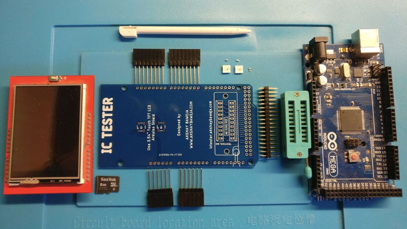
[Akshay] walks readers through the components and assembly of his IC tester, which takes the form of a Shield for the Arduino Mega 2560. The custom PCB he designed and had manufactured holds the 20 Pin ZIF Socket as well as the 2.4 inch TFT touch screen. The screen features an integrated micro SD slot which is important as you need the SD card to hold the chip database.
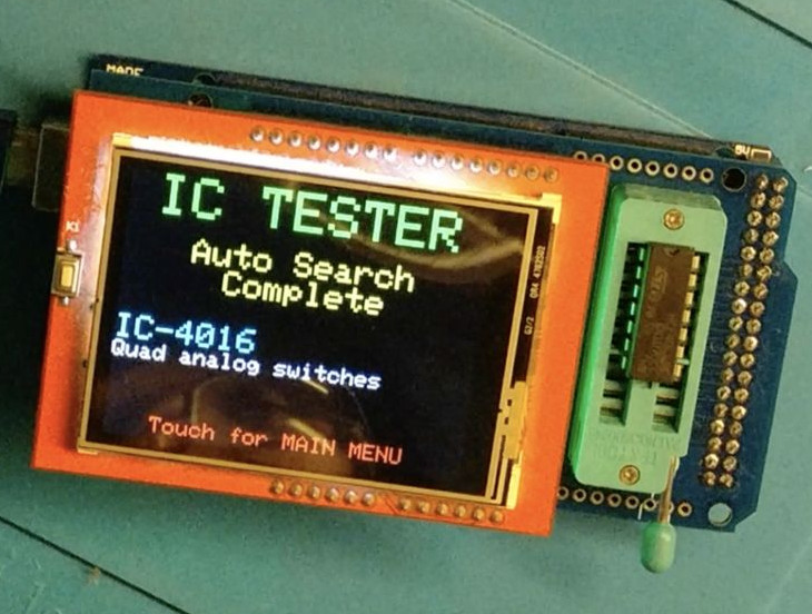
With an IC to test inserted into the ZIF socket, the user can have the tester attempt to automatically ID the chip or can manually enter in a part number to lookup. The source code for the Arduino as well as the chip ID database is up on GitHub for anyone looking to add some more hardware to the device’s testing repertoire.
The importance of good test equipment simply cannot be overstated. Between highly specialized gear like this IC tester to classic instruments such as the oscilloscope, your bench is going to be full of weird and wonderful pieces of equipment before too long.


Cool! If I can figure out the database it could be updated to have more chips added. There are IC testers with LCD on eBay (for example) for under $30 but they do not have an ability to detect unknown chip.
One small point – best would have been to use two arduino pins connected to each chip pin – one directly, one through small resistor – that would have allowed to check if it is input or output pin, and also detect “nothing inserted” state.
It looks like there are plenty of unused pins, 14-21 along the top row of the Mega, and I’m willing to bet the LCD doesn’t use all the pins it sits atop. You could do this and fork the code.
https://m.youtube.com/watch?v=7Br3L1B80ow
That LCR tester is quite good, but it’s a different beast. IC tester tests ICs and, to my knowledge, only ICs. The LCR tester tests only passive components and different types of transistors (can’t really test many chips with only 3 test pins). LCR tester and this IC tester would go good together.
The IC tester is still lacking a feature. It test the chip and then confirms if it’s the chip (in manual mode). What if i have a chip, that i know is a quadruble AND-gate chip and one of the gate or pin is broken? The tester seems to say, that it’s not the chip instead of telling where the test failed. But perhaps in the future. Thumps up anyway.
I would think if you tested IC using known number and it reports fail, assume the IC is bad. There’s little reason to keep a chip that has only 3 working AND gates plus 1 bad gate. How are you going to mark it? Tiny print “Do not use pin 1, 2, and 3”
Well, yeah, i understand that mostly you would just junk the broken chip, unless you really need it now and only need the 3 or less gates.
To mark it, you could just cut the pins.
But also another thing is if you are testing a chip removed from a machine, you could know if the gate, that you suspect is not functioning. That way you could verify you analysis better. There could be importance to know, if the whole chip fried or only that one gate.
Dave “pretended” not to know what it was. It’s only the 8th all-time most popular thread on his own forum. He gave it a negative-ish review. Maybe how he thought it would generate more youtube views or something?? He’s been click baiting for a while now.
You pretend to actually know something about Dave’s videos. >_>
I find his videos are spot on with their descriptions, and on delivering what’s promised. You need to learn the definition of clickbait, cause you have NO CLUE what you’re talking about. Dave vids are NOT clickbait.
Dave also clearly stated what he THOUGHT the thread was about… Simple transistor testers, like what some cheapo multimeters have. Dave has always considered those to be a gimmick. He had ignored it because he didn’t know the LCR transistor testers did more than basic bipolar transistor testing. Once he eventually looked into it (due to the thread’s popularity), and ultimately realized there was some interesting things going on under the hood, to get some wide feature claims, he finally investigated it.
Naw… I suspect you’re just one of those types who prefers just one or two particular types of videos Dave makes, and have nothing better to do than just complain non stop when he’s between you’re favorite content, putting out videos on other things.
Dave and his videos have more integrity than most Youtube channels. He don’t let donations mar a review, even if it’s a bad one. He delivers on what he says. Grow up. You don’t even KNOW what the word click bait means. It’s nothing more than a catchphrase insult to pass against someone you have a beef with.
“$300,000 Dumpster Dive”
I like Dave, but to say his videos are not clickbait isn’t exactly accurate either.
That was April Fools -.-
Oh, my God… That was a joke. That was OBVIOUS. So you are going to say that because of ONE joke video, his whole channel is “clickbait”. You are hopeless, and I’m done talking with you… If I continue, I’m only going to forced to insult your intelligence or say something I would rather not. I’m sorry to hear you’re not cut out for social interaction with others in the real world…
This is the first thing I thought of when I saw this post as well.
I did something like this to program FLASH chips –
https://hackaday.io/project/6275-quick-and-dirty-parallel-flash-programmer
https://cdn.hackaday.io/images/3834621434189803197.jpg
You could probably cost-down this IC tester further by using a simple socket like above and use the serial monitor instead of the LCD.
It could also be extended to be used to test RAM chips and program FLASH etc.
The data base is invaluable, nice work.
I fully agree. I have to many single purpose devices filling up my workbench already. Nontheless kudo’s to [Akshay Baweja] for a very nice project.
how hard would it be to make something to test all the IC/ram/cpu of retro computer and console hardware from the 80s/90s?
Question: I keep seeing silicon pad popularity.Silicone gets static charged so why on earth(sic!) use it for sensitive electronics? What I’m missing?
a regular engineering silicone pad is self healing so you can work on it and it’s supposed to last a long time. i happen to know from watching dave jones that his are esd pads. they are basically a gigantic diode and there is an earth connection on the back and they prevent build up of static.
They are silicone not silicon :-)
Second sentence mate.
I’m not talking about ESD grounded mats with clip.On the photo, there is cast silicone mat.
Heat resistant, to the point where one can use hot air, or solder without melting the anti static mat underneath.
Non slip, so stuff tends to stay put while working on it.
Non conductive, so no shorting.
Flexible, so dribbles of glue/flux etc do not harden and become part of the mat.
They are handy things to have. Not for every purpose, or every component, but nothing is.
I have an anti static mat on my bench, but use a cutting mat, or a silicone one on top when appropriate.
The blue silicone are insulators, so I don’t know why, when you can get black ESD dissipative silicone mats that are as good as the blue ESD mats.
Hmm; It’d be interesting to see if this could be connected to the internet (either via a wifi adapter, or through a port to something like an ESP32), so a larger, external database (EG octopart) could be used
Probably. But with the 4GB SD card on there, seems you would be better served just pulling down a mirror of whatever chip ID databases are out there and keeping it on the local device so you don’t have to keep calling out to the Internet.
I’d hate to have my test equipment fail on me just because I don’t have the WiFi encryption key.
Do Octopart have data that can be used to test a chip? I.E machine-usable state diagrams and pinouts?
Maybe he could get Peal elec to make finished product out of it? Would be a nice addition to their nice range of simple but effective testers. No I do not work for them, but I use the testers)
Really cool, but how do you test for unknown ICs (without frying them)?!
Years ago, I made an IC tester using an 8080 trainer system to test the drawers full of 7400 series ICs used in lab experiments at the college lab where I was taking courses. I’d come across bad ICs and bad gates on the ICs during lab exercises, undoubtedly due to abuse by students over time, so I decided to quickly test every 7400 series the lab owned. Of course a ZIF socket was used, a two digit number was input to set the IC type to be tested, the test button pressed and a GO or NO GO LED was lit, next IC of same type was inserted, repeat. Another button was pressed to change IC type. The program was written in machine code which is all that the trainer allowed.
so, after looking at the code, i’m pretty sure he iterates through the list of chips, and on the way to finding a match he drives pins high and low all over the place directly from atmega pins.
don’t get me wrong, this project has potential, but i’m not sure i’d recommend doing it this way.
shorting atmega pins or pins of the dut just isn’t a good idea.
at least put in some resistors and check the voltages to make sure you don’t drive against an output.
Probably just current limiting resistors on every pin since those chips shouldn’t use more than a few milliamps
Except it doesn’t. Did you check out the schematic? There are no current limiting resistors. I’d be concerned that this will eventually damage both the ATMega and the chips being tested. Many older chips suffer from parasitic SCR latchup if the pins are powered up in the wrong order.