Turning The Raspberry Pi Into A MCU Programmer

Once you graduate beyond development boards like the Arduino or Wemos D1, you’ll find yourself in the market for a dedicated programmer. In most cases, your needs can be met with a cheap USB to serial adapter that’s not much bigger than a flash drive. The only downside is that you’ve got to manually wire it up to your microcontroller of choice.

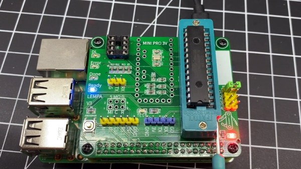
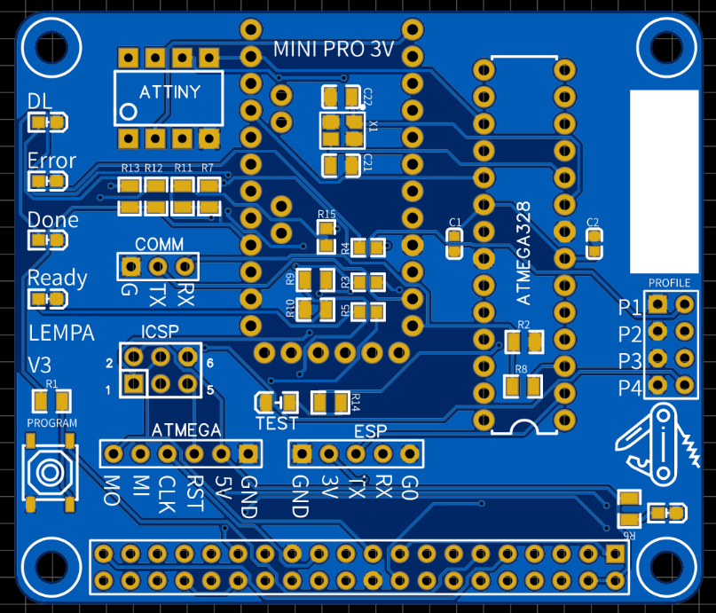
Unless you’re [Roey Benamotz], that is. He’s recently created the LEan Mean Programming mAchine (LEMPA), an add-on board for the Raspberry Pi that includes all the sockets, jumpers, and indicator LEDs you need to successfully flash a whole suite of popular MCUs. What’s more, he’s written a Python tool that handles all the nuances of getting the firmware written out.

After you’ve configured the JSON file with the information about your hardware targets and firmware files, they can easily be called up again by providing a user-defined ID name. This might seem overkill if you’re just burning the occasional hex, but if you’re doing small scale production and need to flash dozens of chips, you’ll quickly appreciate a little automation in your process.

Of course, if you’re just trying to flash some code in a pinch, there are some more expedient options out there. We’re particularly fond of using a development board to program the bare MCU.

Continue reading “Turning The Raspberry Pi Into A MCU Programmer”

Building An Arduino Smart IC Tester For $25

There’s no question that you can get a lot done with the classic multimeter; it’s arguably the single most capable tool on your bench. But the farther down the rabbit hole of hacking and reverse engineering you go, the more extravagant your testing and diagnostic gear tends to get. For some of us that’s just an annoying reality of the game. For others it’s an excuse to buy, and maybe even build, some highly specialized equipment. We’ll give you one guess as to which group we fall into here at Hackaday.

[Akshay Baweja] is clearly a member of the second group. He’s recently published a guide on building a very slick intelligent Integrated Circuit tester with a total cost of under $25 USD. Whether you’re trying to identify an unknown chip or verifying your latest parts off the slow-boat from China actually work before installing them in your finished product, this $25 tool could end up saving you a lot of time and aggravation.

[Akshay] walks readers through the components and assembly of his IC tester, which takes the form of a Shield for the Arduino Mega 2560. The custom PCB he designed and had manufactured holds the 20 Pin ZIF Socket as well as the 2.4 inch TFT touch screen. The screen features an integrated micro SD slot which is important as you need the SD card to hold the chip database.

With an IC to test inserted into the ZIF socket, the user can have the tester attempt to automatically ID the chip or can manually enter in a part number to lookup. The source code for the Arduino as well as the chip ID database is up on GitHub for anyone looking to add some more hardware to the device’s testing repertoire.

The importance of good test equipment simply cannot be overstated. Between highly specialized gear like this IC tester to classic instruments such as the oscilloscope, your bench is going to be full of weird and wonderful pieces of equipment before too long.

Continue reading “Building An Arduino Smart IC Tester For $25”

Fixing An NES For Good

Sometime in the late 80s, the vast collective consciousness of 8-year-olds discovered a Nintendo Entertainment System could be fixed merely by blowing on the cartridge connector. No one knows how this was independently discovered, no one knows the original discoverer, but one fact remains true: dirty pins probably weren’t the problem.

The problem with a NES that just won’t read a cartridge is the ZIF socket inside the console. Pins get bent, and that spring-loaded, VCR-like front loader assembly is the main point of failure of these consoles, even 30 years later. You can get replacement ZIF sockets for a few bucks, and replace the old one using only a screwdriver, but this only delays the inevitable. That ZIF socket will fail again a few years down the line. Finally, there is a solution.

The Blinking Light Win, as this project is called, replaces the ZIF connector with two card-edge slots. One slot connects to the NES main board, the other to the cartridge connector. There’s a plastic adapter that replaces the spring-loaded push down mechanism created for the original ZIF connector, and installation is exactly as easy as installing a reproduction NES ZIF connector.

If you’re wondering why consoles like the SNES, Genesis, and even the top-loader NES never had problems that required blowing into the cartridge connector, it’s because the mere insertion of the cartridge into the slot performed a scrubbing action against the pins. Since the ZIF socket in the O.G. NES didn’t have this, it was prone to failure. Replacing the ZIF with a true card-edge slot does away with all the problems of dirty contacts, and now turns the NES into something that’s at least as reliable as other cartridge-based consoles.

Add Features (that Should Have Already Been There) To An EPROM Programmer

extending-an-eprom-programmer

[Morten Overgaard Hansen] has a cheap EPROM programmer which he uses to program chips for retro gaming (among other things). He was surprised that although the device includes a 40-pin ZIF socket it seems to lack the ability to program 16-bit chips. He figured he could get it to play ball if he put in a little effort. Above you can see that a few add-on parts enabled 16-bit programming on the device.

If you look inside the case you may be surprised to find it uses an FPGA. [Morten] searched around and found a few others online who had been looking to stretch the functionality of these types of programmer. Specifically, he came across a Python program for this programmer’s bigger bother that already implemented the functions necessary to program the larger chips. He used it as a guide when writing his own programming application.

On the hardware side of things he needed to feed a higher voltage to the VCC pin, which is done with the boost converter seen to the right. He also added some jumper wires to manage the output enable signal. To make the whole thing modular he ordered a ZIF socket with long pins and soldered the alterations in place. Look closely and you’ll see two levers for ZIF sockets. The one on the right is for the original socket, the one on the left is for the adapter.

Business Card AVR Board Updated

bcard

Evil Mad Scientist Laboratories has updated their business card AVR breakout boards to version 1.1. We suspect the changes will probably make them even more popular. The boards are designed for the ATmegaXX8 family of microcontrollers. The center has all 28 pins labeled while either end has a prototyping area. An in-system programming header is also provided. For the new version, both prototyping areas have been increased to accommodate DIP14 packages. The holes for the microcontroller are now larger so that they can hold a ZIF socket. Finally, the power and ground traces have been expanded. We’ve always like the versatility of these boards, as demonstrated in the Tennis for Two project, and can’t help wondering if these updates were made to facilitate another project.