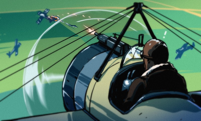
Early airborne combat was more like a drive-by shooting as pilot used handheld firearms to fire upon other aircraft. Whomever could boost firepower and accuracy would have the upper hand and so machine guns were added to planes. But it certainly wasn’t as simple as just bolting one to the chassis.
This was during World War I which spanned 1914 to 1918 and the controllable airplane had been invented a mere eleven years before. Most airplanes still used wooden frames, fabric-covered wings, and external cable bracing. The engineers became pretty inventive, even finding ways to fire bullets through the path of the wooden propeller blades while somehow not tearing them to splinters.
Early Aerial Combat
At the start of the war, aerial combat involved pilots firing bullets at each other using handheld pistols or rifles and even throwing out rope to tangle the enemy’s propeller. The pistols were inaccurate and the rifles had a small chance of hitting a critical component. With the pilot both trying to fly the plane and fire a weapon at the same time, none of this was very effective.
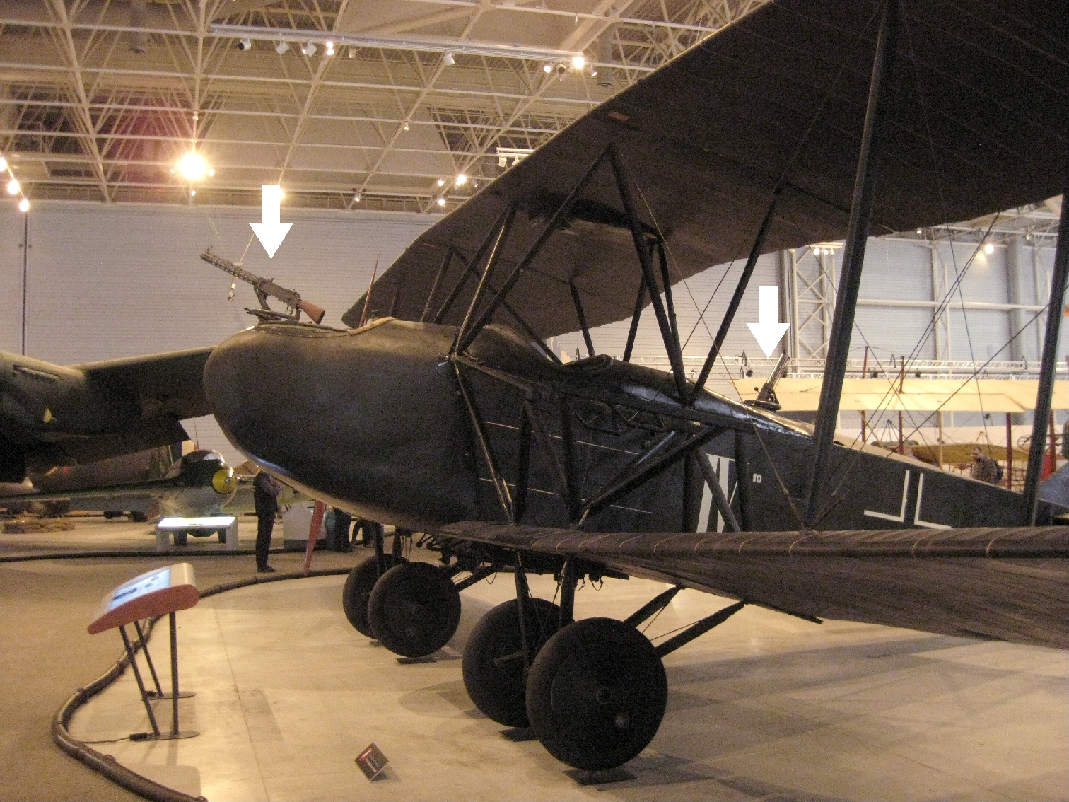
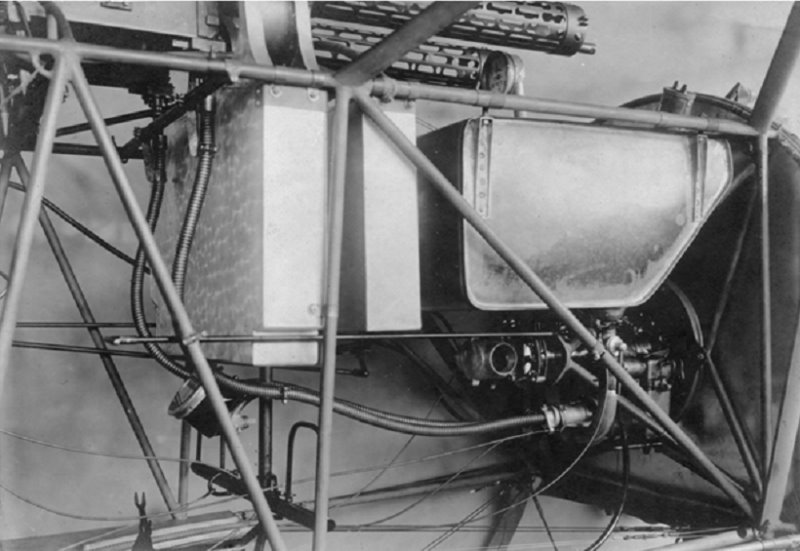
It was when machine guns came into use in the latter part of 1914 that aerial combat really began. Some larger aircraft did carry dedicated gunners, such as the German AEG G.IV bomber pictured here but dedicated fighter craft carried just the pilot.
You may ask, why not mount forward-facing machine guns onto the wings? During World War I wings were braced using cables and didn’t provide as rigid a mounting position as the fuselage, resulting in vibrations which reduced accuracy. Also, with the guns so far away, the pilot couldn’t clear jams or reload. Though with later multi-crewed bombers, mechanics did often venture out onto the wings to perform maintenance.
Firing Over The Propeller
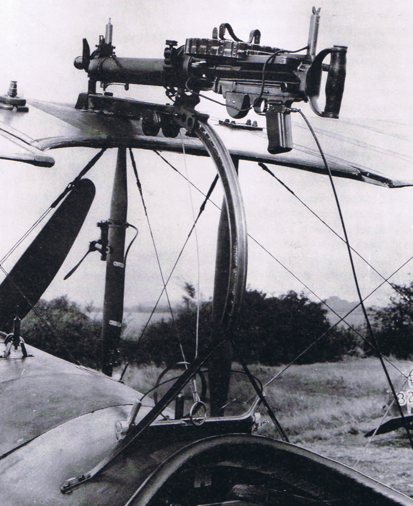
For biplanes, the upper wing offered a location to mount a forward facing machine gun which would fire above the propeller. Being on the wing instead of the fuselage, it did lose accuracy due to vibration. But it allowed the pilot to both steer the plane and fire the gun at the same time. The British Foster mounting shown here was one such example.
The machine gun was mounted on a curved rail so that it could be pulled down by the pilot for clearing any jams and reloading. It could then be raised back up through a combination of springs and bungee cords.
Pilots found that they could also fire with the gun partway along the rail, such that it was pointing upward. This allowed them to shoot at the enemy from below and to the rear.
Deflecting Bullets Fired at the Propeller
The most effective and preferred single-pilot fighter aircraft machine gun mounting was in front of the pilot on the fuselage where vibration was at a minimum. The pilot could steer the plane and aim the gun by the same action and could clear jams and reload. However, there was the small issue of having a propeller in the way. It would not do to cut away the ends of the wooden blades in mid-flight. Surprisingly, the first solution wasn’t really a solution at all but more of a hacked-together workaround.
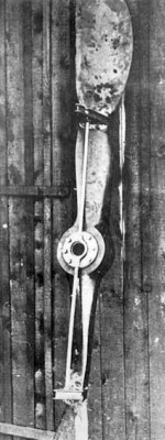
One way to at least minimize propeller damage was to mount a steel wedge to the backside of the blades in line with where the bullets flew. Any bullets which hit it were deflected to one side. Shown here is a propeller with the wedges mounted at the correct radial distance from the center and with tiebars for bracing. This one was used by Roland Garros in April 1915 as a backup for the synchronization approach I talk more about below. While he scored several kills, he was forced to land due to engine failure, possibly caused by strain on the engine’s crankshaft by the bullets striking the deflectors.
But besides putting a strain on the engine, deflectors caused another problem. The propeller blades were typically made of laminated wood and the impacts, despite being deflected away by the steel deflectors, would cause the glue to weaken and the layers to separate. It was therefore preferable to avoid hitting the propeller.
Firing Through The Propeller: The Engine Literally Pulls the Trigger
Syncronization was the answer to avoid having bullets hit the propeller. One of the earliest mechanisms devised was the Fokker Stangensteuerung gear. It used a cam on the propeller shaft to push on a rod which pushed the gun’s trigger.
The cam was aligned to only fire when the path for the bullet was clear. Of course the gun shouldn’t fire every time the engine is turning, so there was a trigger lever which the pilot had to press to as a final part of the firing mechanism. The video below of a museum exhibit shows the mechanism in action but there are some subtleties which the following diagrams make clear.
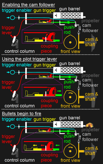
Enabling the cam follower: The system included an enabler mechanism that disconnects the cam follower to minimize wear. When it’s time for combat, the pilot pushed the trigger enabler forward, lowering the cam follower so that it can contact the cam. Note that at this point the pilot isn’t pressing the trigger lever and so the coupling piece remains pivoted up. As long as the coupling piece is pivoted upward, the push rod and coupling piece are prevented from pushing on the gun trigger.
Using the pilot trigger lever: When the pilot wished to fire the gun, he pushes on the trigger lever which pivots the coupling piece down. Note that depending on where the cam is in its rotation, the gun trigger may be in the way of the coupling piece pivoting down (as it is in the first diagram). But at some point in the cam’s rotation, the push rod will have pulled the coupling piece in the direction of the propeller far enough such that the coupling piece can pivot down. But the gun doesn’t fire yet.
Bullets begin to fire: The gun fires at only one point during the propeller’s rotation: when the bump on the cam is under the cam follower. When the bump pushes the cam follower up, the cam follower pushes the push rod toward the pilot, in turn pushing on the coupling piece which pushes on the gun trigger which fires a round in the gun. The cam’s alignment ensures the bullets pass between propeller blades.
The following video shows the synchronization gear of a German single-seat Fokker E-type monoplane. This is from an exhibit once on display in the Canada Aviation and Space Museum and simulates all the above actions as well as showing how things are restored to a non-combat stance after a battle.
Difficulties with Synchronization Propeller and Machine Gun
There were some difficulties with the synchronizers, as you’d expect of any mechanical system functioning at such a high rate of oscillation.
Temperature changes in the metal rods caused thermal expansion which resulted in their changing length. With such tight timing requirements, this would fire the bullet either sooner or later enough to hit a propeller blade.
Propeller speeds also varied during the flight. While you might think that it wouldn’t matter since the cam rotated at the same speed as the propeller, the firing of the gun took a length of time which was independent of the propeller speed. Even the distance the bullet had to travel was an issue with low muzzle-velocity guns and when the travel distance was sufficiently large. With some systems, the pilot had to keep an eye on the tachometer indicating the engine speed to know when it was safe to fire.
If all the above could be solved, many attempts to build synchronizers still failed due to the unreliable timing of many makes of gun. Even inaccuracies in bullet manufacturer meant that some bullets would fire at the wrong time, hitting a propeller blade.
Other Synchronizers
Many synchronizer designs were developed during the war, some which introduced improvements. The German Fokker Zentralsteuerung gear did away with the cam and pushrods and instead connected a flexible drive shaft to the engine’s camshaft. This carried the rotation up to the gun itself.
Timing adjustments could now be done at the gun instead of at a single cam on a propeller shaft. This was especially useful when multiple guns were used in order to maximize the chances of hitting a critical part of the enemy plane. A separate flexible drive shaft was run up to each gun. Since each gun had slightly different timing, this meant that each could be adjusted individually. Also, should one gun fail, the others would still work.
Yet other means of synchronizing with the propeller position were electrical, using contacts around the propeller shaft to activate a solenoid at the gun trigger, and hydraulic. A modern implementation by a hacker would of course use a microcontroller and an airsoft gun.
The End Of Synchronizers
A number of things brought about the end of synchronizers. One was that the increased speed of aircraft made them harder to shoot down at the synchronizer’s firing rate. More powerful bombers used heavier armor for vital areas which rifle-caliber machine guns were unable to penetrate. The switch from cable-braced wings to the more rigid cantilever wings meant that guns could be mounted on the wings instead. And of course, the eventual introduction of jet engines meant there were no more propellers to fire through. The final synchronized guns were used during the Korean war in the early 1950s.


This brilliant invention changed air to air combat almost overnight. It seems an obvious solution now after the fact but back then, it was sheer brilliance.
The original bump stock…
Slo mo guys have a video on this, if someone pots the link……
https://youtu.be/ysB-SH19WRQ
Thank you
The P-39 Aircobra had a cannon that shot through the propeller hub, though that was an exception.
The Me-109 did as well.
A Japanese fighter of the same WWII era as well, IIRC.
In those cases the propeller shaft was offset from the crankshaft to allow the cannon to pass through.
You think someone would have come up with shooting through the centre of a radial engine.
You would have to shoot through the crankshaft and the connecting rods. The ME109 shot a 20mm cannon through the hub of it’s propellor, but the engine drove the propellor through a gear system, so the crankshaft was offset from the propellor.
No firing down the center axis of the engine. Ultimate, point and shoot.
There’s something I don’t understand about the museum video. Was there an airplane that rotated the entire engine with the prop?
The Sopwith Camel rotated the block and propeller, with the crankshaft fixed to the plane.
The fuel and lubricant entered through the crank shaft.
The extra rotating mass made it difficult to turn the plane against the spin, so enemy pilots soon learned which direction their quarry would turn.
(Most of?) the airplane engines of that time did not have an oil sump, so oil was either burned with the fuel or spun off through the various leaky seals. That is why their pilots wore goggles and a scarf. The scarf was used to wipe the oil spray off of the goggles.
Even worse…
The primary oil used for many of these engines was Castor oil, which has useful medical side effects. Not shown in the movies, latrines were stationed at the ends of the runways so pilots could make immediate use after missions.
Now there is an image that doesn’t come to mind when you think of the devil may care WWI Ace.
BOMBS AWAY!!!
LMAO!
Only if the pilot was lucky enough to even make it that far before “dropping the bomb” as it were. (Or getting shot down, but that’s another matter
+1
s’up biggles (anyone ever seen the 90’s movie?)
Look up aircraft rotary engine. There were several where the crankcase and cylinders rotated.
There were several engine designs that did just that.
Many did this. the cylinders rotated around a fixed crankshaft. It helped with cooling and oil delivery.
Oh yeah. There were a couple motorcycles built that way too. Whole radial rotary engine encased in the spokes of the front wheel:
https://upload.wikimedia.org/wikipedia/commons/9/92/110_ans_de_l%27automobile_au_Grand_Palais_-_Megola_640cc_Touring_Model_-_1922_-_003.jpg
Why aren’t the motorbikes of today as good looking?
Today it’s all about building as many as you can very few care about taking time to build sleek one of a kind machines
Small correction. WWI spanned 1914 – 1918.
Oops. Fixed. Thanks.
There is a great wikipedia article about this for those interested:
https://en.wikipedia.org/wiki/Synchronization_gear
See this excerpt from a roadrunner cartoon. (“Just Plane Beep”) https://www.youtube.com/watch?v=hOwN_L3j8iU&t=1m12
There may also have been a Disney cartoon that illustrated the problem.
Hey Guys,
For those interested, that display in the youtube video is at the Canada Aviation and Space Museum same as the Junkers aircraft pictured in the article. I work as an electronics tech. at the museum and am currently repairing that interactive (which has been in service since the late 90’s). I’ve been a long time reader of HaD and thought it was neat to see my work featured on the site.
Cheers,
Jon
Hi Jon,
My memory of seeing that interactive working at the museum around 20 or so years back is what gave me the idea to write this article. I’m glad to hear it’s being repaired.
I love that museum. That new ISS model (new to me) I saw when I recently visited to do research blew me away. The Canadarm display was a new treat too. The place is full of great exhibits.
Keep up the great work,
Steve
I knew it. Unfortunately that display is broken every time I’m at the museum.
Yeah its been busted for quite some time now, I’ll see if I can remember to update this comment when I have finished the overhaul.
The other development that changed things was the fabrication of metal propellers that wouldn’t delaminate/break if they picked up a bullet hole. There are several accounts of WWII pilots in trainers (particularly the AT-6) that would occasionally put a hole in the propeller because of the synchronizer system misfiring The solution to this was to clean up the hole, and drill another just like it in the opposing blade for balance and go back to flying. I have read that the propellers were retired after three shots, but can’t verify that.
“low muzzle velocity”?? From what I recall, the 7.62×63 and 7.92×57 were running over 2500fps, with the 303 British in the same range. 8mm level might’ve been somewhat slower, but not by a lot. (2100-2200fps maybe?)
Next thing to learn:how to make a good strong propellor
I think big part of getting the weapon near line of eye-sight of the pilot was to get the error down caused by axially offset.
If the weapon is far away from gunsight you could only adjust it good to a small range extend. Getting it in front of the pilot eases that problem.