
If you open up the perennial favourite electronics textbook The Art Of Electronics and turn to the section on transistors, you will see a little cartoon. A transistor is shown as a room in which “transistor man” stands watching a dial showing the base current, while adjusting a potentiometer that limits the collector current. If you apply a little more base current, he pushes up the collector a bit. If you wind back the base current, he drops it back. It’s a simple but effective way of explaining the basic operation of a transistor, but it stops short of some of the nuances of how a transistor works.
Of course the base-emitter junction is a diode and it is not a simple potentiometer that sits between collector and emitter. The “better” description of these aspects of the device fills the heads of first-year electronic engineering students until they never want to hear about an h-paramater or the Ebers-Moll model of transistor function again in their entire lives. Fortunately it is possible to work with transistors without such an in-depth understanding of their operation, but before selecting the components surrounding a device it is still necessary to go a little way beyond transistor man.
The Simplest Biasing Example
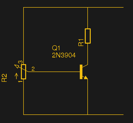
Imagine for a moment a simple transistor circuit involving a single NPN transistor with its emitter grounded, its collector tied to the positive supply by a resistor, and a potentiometer between ground and supply allowing any voltage to be supplied to the base. Because the emitter is grounded, even if sometimes via a resistor, this transistor configuration is referred to as a Common Emitter amplifier. In this circuit if you were to start with the potentiometer at the grounded end then the transistor would be turned off, and no current would flow.
In an NPN transistor, the connection between base and collector is a PN junction, so as you might expect it shares its properties with the PN junction in a diode. A silicon diode starts to conduct when the voltage across it reaches about 0.6 V, and when the voltage from our potentiometer across our base-collector junction reaches 0.6 V, it also starts to conduct. A small current flows into the base, and since this is a transistor we’re talking about that results in a larger current flowing through the collector. We’re back to the little man in the Horrowitz & Hill cartoon, and the relationship between base current and collector current is called the transistor’s gain. You will see it quoted on data sheets, and for example a transistor with a gain of 100 would pass 100 mA at the collector for a base current of 1 mA.
When the base voltage is just over 0.6 V, a little current flows in the collector, but not much as the transistor is barely turned on. As our potentiometer moves upward the base voltage will increase, and there will be a corresponding increase in base current with an attendant increase in collector current. There will be a region during which the relationship between base current and collector current is close to linear, but eventually a point will be reached at which the collector current stops increasing no matter how much you increase the base current. At this moment the transistor is said to be saturated, or fully turned on, passing a current that’s limited by R1.
Making a More Practical Amplifier
Now, imagine for a moment our simple DC circuit used as an AC amplifier. We’re keeping the potentiometer, but also applying an AC source, a sine wave, to the base. As our sine wave rises and falls, so does the base voltage, and thus its current. If the base is held at the just-turning-on point of 0.6 V then the transistor will only be turned on during the upper part of the cycle, and if it is held near the transistor’s point of saturation then the transistor will only pass through the lower part of the cycle. In both cases half the cycle is missing at the collector. To amplify the whole cycle of our sine wave we must therefore hold the base with our potentiometer such that the transistor is in that close-to-linear region over the whole range of base current generated by the sine wave. Holding the base voltage of a transistor in this way is referred to as biasing it, and a transistor with this type of biasing will pass a constant standing current through its collector when connected to a supply and with no incoming signal such as our sine wave.
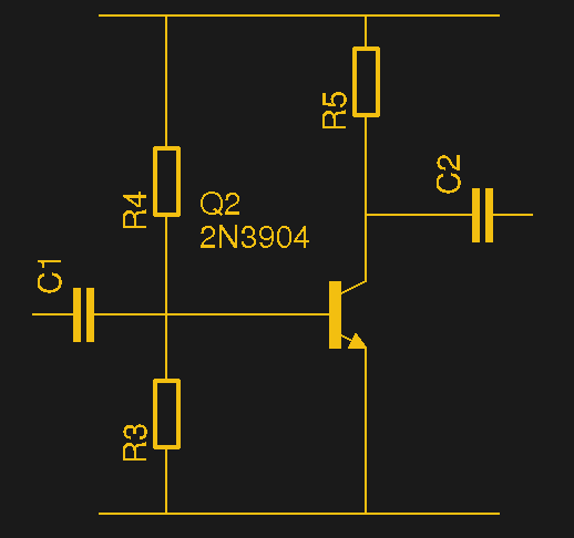
The classic transistor amplifier circuit then has a pair of resistors in series between supply and ground, forming a potential divider that gives the base its bias. The emitter is grounded, and another resistor lies between collector and the supply. A small incoming signal is provided to the base, and an amplified and inverted version of it appears at the collector. There are many variations and refinements of this circuit involving emitter resistors and bypass capacitors to modify the high-frequency response, but this simplest of circuits should be enough to understand its operation.
How then does one arrive at the values for the various resistors? For the dedicated mathematicians there are a set of formulae which can easily be found online and which it is better not to cut-and-paste here in the pretence that I and many other engineers have even given them a second look since university. For most others designing from first principles there are innumerable pieces of circuit analysis software, many of which trace their lineage from the venerable SPICE. I have met engineers who learned SPICE through the medium of punched cards, I learned it through a terminal into a VAX minicomputer, count yourself lucky if your introduction to it was through a desktop GUI. My simulator of choice, just to name one, is QUCS.
As always though, there is an “official” answer, and an “unofficial” answer. Do I reach for QUCS every time I wire up a 2N3904? Of course not. Like all who have gained familiarity with something through long practice, I imagine myself to be cleverer than SPICE. So I make a few guesses, then breadboard the resulting circuit, and make a tweak here or there if it isn’t quite right. For example I’d pick a collector resistor using Ohm’s Law to deliver the desired maximum current when the transistor is saturated, then make a few guesses with the bias resistors by making their total value over 10 times the collector resistor and the ratio of upper bias resistor to lower one being about 2 to 1. You can make hay in the comments and poke it full of holes based on your simulations, experiments, or experience, but this is really an exhortation to all readers to have a go and experiment with biasing in their own circuits.
Self-biasing, a Much Simpler Option
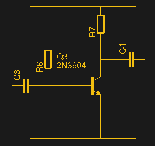
If a potential divider is too complex for you, there is another option. A so-called self-biasing circuit replaces the potential divider with a single high-value resistor (R6) from collector to base.
This circuit works on the principle that the base resistor is chosen to supply just the required current to turn the transistor on such that it remains in that just-about-linear region mentioned earlier. The base resistor is thus usually of a high value, typically in the several hundred kiloohm range. In the days of germanium transistors you would even see circuits without a bias resistor that relied on the higher leakage current of germanium devices, if you read our recent piece on [Clive Sinclair]’s writing you might have seen an example in one of the figures. As before if you prefer not to simulate it you can calculate the value of the base resistor depending upon the base current required to deliver your desired collector current, but again it’s a simple circuit to guess a resistor value for. A 1 kΩ collector resistor and a 330 kΩ base resistor has never failed me for a small-signal self-biasing audio amplifier, I’m nothing if not a creature of habit.
A month or so ago I wrote a piece bemoaning the lack of electronic fundamentals such as transistor biasing in a generation brought up on the Arduino or the Raspberry Pi. They are lucky enough to come out of their teenage years with useful skills such as the internals of a GNU/Linux OS or the intricacies of SPI interfacing, but analogue electronics at this level simply hasn’t come their way. This has been in part an attempt to address that problem, as well as something of a homage to the single transistor amplifier. I don’t by any means claim to have provided a comprehensive introduction tot he subject, but that handily leaves the door open for the chance to return in the future. Meanwhile if any of you have never picked up a 2N3904 and experimented with it rather than following someone else’s circuit, I hope you’ve been given some encouragement. Good luck!


The “transistor man” lives in a MOSFET too, but he has a voltmeter instead of an ammeter.
I prefer the term ‘transistor individual’
2nd Edition, p. 64: “Transistor man”. I’m not embarrased to admit that I checked while editing the article.
Bloke. Every time.
Should we call him “Transistor Bloke” instead? Has a nice ring to it, especially if read in the voice of [James May].
My suggestion was deleted by the Evil Overlords…
@Ren:
Your comment was not deleted by us. Your comment, which was (in its entirety, “Why not Transistor tranny?”) was reported enough times by the community that it was kicked off to moderation. I shoved it in the trash, because I’m a man of the people.
@Brian Benchoff
Some people still call transistors “trannys” for short (vocally short), but this isn’t common anymore thanks to political-correctness and SJW’s.
Additionally, it could be only one offended person out of the billions of people on our planet… all it takes is for that person to open the tor browser (a simple unpack once and run many affair)… then perform a:
(ctrl+shift+U) + (ctrl+l) + (ctrl+v) + report comment (repeat)
The current setup for community reported comments is merely just a fixed number of reports.
What it should be is a percentage of the daily average comment submissions.. i.e. 5% should get the comment looked at and 30% should get the comment immediately removed.
It is like having a football stadium full of football fans and having five people outside protesting that football games are torturing the players… and then banning football games for good! The insignificant get what they wanted and the many suffer. (P.S. political correctness gone extreme is a hot topic between the many quieter voices).
Just tested it… It takes six goes as usual and only took me about 2 minutes*…. shouldn’t that barrier of reporting comments be higher Brian? You know… to make it not worth the efforts of those SJWs whom spamm the report comment link?
* 2 minutes is enough time to waste whilst waiting for some cooked food to cool after turning off the hob before serving, thus in their eyes… not time wasted.
Bearing in mind I used details from a comment post that is the original Schlem and thus the e-mail may no longer be valid or etc…. just like many of the fake handle details I create… unless I completely make up the details.
Also as far as Tor, proxying and using hacked routers for VPN-ing over… It is impossible for I to be tracked or blocked… I’ll just hack another IP, I’ll just use another handle and I’ll just find another way. I have a hatred for those self-righteous millennial-esque based SJWs whom try to make even breathing illegal if nobody else but them is them.
[schlem]
I just chalk it down as another example of “tyranny by the minority”
oh no the “SJWs” came for the extremely useful and helpful comment “transistor tranny”
תל אביב I thought that swj meant single Jewish women
Another original art saved on “collection to print” catalog, thx ;)
The second schematic in the article is a fundamental example why you never make 4 way wire junctions – for junctions to be unambiguous, they must always be T junctions. 4 way junctions should have an offset and thus be a pair of Ts.
It would also be unambiguous if the junction was marked with a dot.
That’s problematic as the dot can sometimes be hard to spot on nth generation copies or if the printer screws up or…
The double T junction is never ambiguous.
So, “nth generation” is still a problem these days? I would have thought that it would have died with the era of the photocopier.
So my biased schematics must also have parity?
I see what you did there…
I’d argue that there is no ambiguity here – the circuit as presented is just wrong.
Indeed! Two wires crossing with no dot is (by convention) NO CONNECTION since at least the 1980’s.
+1 All dots are missing
But there’s a dark grey ring around it! Can’t you see it?
If you think you can just assume that that is the convention, you should start remembering to read the datasheets! ;)
Wait, no dot means a connection exists w 4 wires?!? WTH(heck) ever happened to jump overs?!? A demanded jump-over coupled w demanded dots is what removes all ambiguity… period. No discussion. Less are lazy conventions for… the lazy and *care-less.*
Well, it’s fairly easy to see what was intended. A resistor divider with no connection in the middle makes no sense.
That way lies madness.
If there’s no connection in the middle then it’s not a divider. It could just be two resistors selected from the standard range to create a specific total resistance – not an unusual thing to do in analogue electronics. It would be more usual for one of them to be a trimmer potentiometer though, but how do you know which symbol is wrong? That’s the point. We only know from context (the text article) what the mistake actually is. What use is a resistance across the power rails? Who knows, but I’m sure someone could find one. Speaking of power rails, they aren’t correctly marked here either. I just checked that circuit in my copies of AoE (pages 57, 70 and 84 in 1st, 2nd, and 3rd Editions respectively for anyone playing along at home), and true to my memory they are all correctly marked. One of the things that has always made AoE stand out from any number of other books was just how fastidiously thorough its authors were. Transistor Man lives on!
Anyway, don’t let my comments detract from the article itself which is enthusiastic, approachable and educational for many. I agree with its author that analogue skills are far too undervalued today, and appreciate the effort here. I see students who can make a robot autonomously move to a specific place counting encoder ticks, or can make string of NeoPixels display any number of pretty patterns, but if I asked them to make a TTL output drive a 12V relay or even just to calculate a current limiting resistor for an LED; they’ll look at me like I grew two extra heads.
And when it is not so obvious? What then?
Bottom line here is simply this: if you never use a 4 way junction like the one shown you will never have this question and debate. If you use only T junctions, again you do not have this potential ambiguity.
So all this debate boils down to, use common sense and avoid 4 way junctions or be prepared to have to argue the point. Whatever your point, be it the quality of printers, copies, poor eye sight, picking the wrong convention, assuming the wrong thing, it is all just a load of wally caused by a bad practice that will always invite this very discussion. And all this silly argument is so easily avoided and life can be so much more straightforward if you don’t spend quite so much of it defending a bad practice but rather spend a tiny amount of your life using a good practice like T junctions. Then perhaps we can get to the substance rather than get stuck on the form.
Just my 2c worth for some otherwise sharp minds buried in a very silly debate.
Well said.
My rule of thumb: If I’m explaining/showing something to an experienced hacker, I take liberties, because I know they will understand.
When presenting a tutorial to newbs, I make everything as clear as I can. There are too many people who call ‘bypass capacitors’ ‘de-coupeling caps’ because someone made a mistake in a tutorial.
Once someone has attained, awareness, granted… a line could miss an inch of photocopier “ink” and be understood. Wait, you could skip the diagram, altogether!!! Not. There is correct convention w dots and jump-overs and lazy-convenience convention.
I cannot see the 4-wire junction that I’d expect… A dot or an offset will show that… At the moment I’m just guessing based on past experience…
However in the self-biasing example:
If you were to replace the R7 with a linear regulator (I used a cheap train speed reg) in Constant-Current mode and a large enough ballast capacitor between reg-out and gnd…
then the point between the transistor and R7 connecting to a large filter capacitor to a speaker to GND… then you have my first power amplifier build (very non-linear I presume).
I used 2x BC109 transistors in darlington config and a fan to cool them: Drove a 3-Ohm 20W cone at around 3 watts and distorting badly at 5W!!!… P.S. after a few months the strip-board had gone a dark shade of brown under the BC109’s
Best practice is to use meatballs (dots) on all joints, and to add offsets so there are only three lines entering any given meatball.
The issue that drives it home is image copying. A few passes through a copier (or printer and scanner) will fuzz a 4-way joint until you can’t be sure if it has meatball or not. You can find lots of that in datasheets for 4000-series logic chips from TI. Even with digital copying, rescaling creates enough blur to make 4-line crossovers ambiguous.
Use of the half-circle ‘hop’ for that lines don’t join is strongly deprecated. It adds clutter to schematics of any complexity, and you can’t hop multiple wires without making it look like an inductor.
Inre: meatballs…
I wish NASA had stuck with the worm.
Thankfully, multi-generation photocopies are hardly ever necessary.these days.
While three junction meatballs are clearly “the right way to do it”, based on the chorus of responses, it appears to be a convention whose original purpose matters less and less.
It still matters because of convention. It =looks= like wires that cross and don’t touch.
And how about hand-drawn schematics?
Half circles also turn to rotten meatballs when copied a few times. I had that problem just yesterday, so it’s still relevant. PDFs can be as bad as photocopies if not scaled properly.
(ticks box on bingo card for “Junctions in circuit diagrams”)
That second paragraph in “The Simplest Biasing Example” is a bit messed up. The first sentence, although technically correct, should really be referring to the base-emitter junction. The second sentence should also be referring to the base-emitter junction unless the “transistor man” is really confused.
Thank you!
I reread that paragraph multiple times and was starting to think that transistors were much harder than I had thought.
I was about to make that very comment.
Forward biased base-collector junctions only happen [in common emitter circuits] when the transistor is saturated, and the voltage across emitter-collector is about 0.2V
You’re right. Missing “it is”, as in “It is not a potentiometer…” Making edit. Surprisingly easy to end up with this kind of thing when you hack around your text.
Jenny, the missing it is isn’t what was being referred to. For an NPN transistor, the base-EMITTER junction is forward biased, not the base-collector junction.
“Of course the base-emitter junction is a diode and it is not a simple potentiometer that sits between collector and emitter.”
Please read it again. Say it, if necessary. We’re talking about two separate parts of the Transistor Man diagram here, the base-emitter junction, which is a diode, and the collector-emitter circuit, which is not a potentiometer. Please tell me where I mention the base-collector junction?
A simple web-page search quickly comes up with:
“. . . and when the voltage from our potentiometer across our base-collector junction reaches 0.6 V . . . “
Or as Don originally stated: That second paragraph in “The Simplest Biasing Example”.
Kind of amazing that you refuse to correct such an obvious error pointed out by so many.
This is still wrong. I just re read that bit like six times and fled to the comments to see if I was crazy or if anyone else picked up on the same error. It would be nice if this was corrected, especially since this article is geared toward beginners and presents some theory.
> fills the heads of first-year electronic engineering students until they never want to hear about an h-paramater or the Ebers-Moll model of transistor function again in their entire lives
Thanks for the reminder, now I get to curl up into a ball and sob for a couple of hours.
“beta times the base current equals the collector current”
repeat ad nauseum
I’d thought that’d be WORSA times if the base current equals the collector current… especially for high current handling transistors…
.
I’ll now run from the angry mob I’ve just accidentally offended :-)
B^)
An emitter resistor is typically included if you want the bias to be stable with temperature. The voltage drop across this resistor should be large enough to outweigh the variation in Vbe over the expected temperature range. The side effect is a reduction in gain, which you get back by bypassing the emitter resistor with a capacitor.
Absolutely. This is more in the realm of the explanatory than the practical though.
Au Contraire, for such a circuit with application prone to heat generation this comment is an amazing useful Gem and impressively insightful to a circuit design newb. I will retain this rule of thumb and its reasoning hopefully for a long time to come,.,
Oh my HaD… The brash simplicity of this post may (and probably will) lead many new-comers down a very deep and dark Rabbit-Hole.
It’s intentionally simple, for accessibility. Think of it as the teenage version of how transistors work. Enough to experiment with, but there is more to learn. I’m not rewriting Horowitz and Hill, instead I’m pitching it at people who know a lot about Arduinos but have never picked up a 2N3904.
Drone hit it now I keep looking over my shoulder
Too.
Thank you Jenny. Simple and inspiring.
You’re welcome. :)
One of the few articles we can say is “biased”. :-p
Lets all find some minutiae to argue about. Awesome article btw. Cleared up some vagueness from school.
This is a great thing, that somebody has taken the trouble to throw some light on analogue electronics. I applaud this and take my hat off to you Jenny.
My only suggestion to improve the first timers experience and success with building this circuit is to add emitter degeneration (as others have noted) to stabilise the operating point, control the gain and to make the circuit more likely to work first go. The analysis is a bit more complex but providing a sample schematic to get them off the ground will then hopefully also give them the motivation to tinker, explore and learn because the thing works right from the get go.
One other thing, sorry, it is two suggestions; the power rail voltage. Give the adventurous minds a head start and tell them what voltage to apply there.
We all want them to succeed and not be discouraged. Bane of my professional life are other engineers who know little about analogue electronics other than some myth and legend that is quoted and applied as though it is universal truth and not just absolute bollocks.
If you can, please keep this up. Feed the inquisitive minds with correct information. You do the electronics world a great service Jenny! Thank you.
I love these “basics” hackaday articles: basic knowledge never gets old
*article about making a buggy whip* :-D
You probably don’t want to know what the kids use it for these days.
Thanks for the article Jenny, I would find the diagrams easier to follow if the power source and ground were labelled. Maybe, the base, emitter and collector as well. Thanks again for the article, much appreciated.
I wish i could run my 3.7v 350ma rc toy off ionizaton pellet ..what im finding is if i get 5v in clean air im getting picoamps so my question is how many smoke dectectors do i need to do this lol…im sick of batteries and recharging them in the wall also weight is a issue on the rc toy so thats why i am not doing solar
Yep. Too many issues with this article, both the diagrams and the text.
Not recommended.
“In an NPN transistor, the connection between base and collector is a PN junction, so as you might expect it shares its properties with the PN junction in a diode. A silicon diode starts to conduct when the voltage across it reaches about 0.6 V, and when the voltage from our potentiometer across our base-collector junction reaches 0.6 V, it also starts to conduct.”
replace collector with emmitter, and you’re good to go.
as it is, it’s just not right.
This is still incorrect in the article. Beginners beware!
I read Art of Electronics several years ago. It’s not a bad book but It is highly overrated. Plenty of much better electronics books out there for both Engineers and Hobbyists. Not sure why its so revered by so many.
[citation needed]
University Level –
Sedra&Smith – Microelectronics Circuits
Sergio Franco – Analog Circuit Design: Discrete and integrated
– Design with operational amplifiers and Analog integrated circuits
Technologist Level –
– Grob’s Basic Electronics
Hobbyist Level –
– Practical Electronics For Inventors
– The ARRL Handbook
Don’t get me wrong The Art of Electronics is a good text as well. It just not good enough to deserve the cult following that it had….which causes even more inflated hype. Perfect example of a positive feedback loop if you ask me
Add to it:
“Foundations of Analog and Digital Electronic Circuits”, Anant Agarwal
They use it at MIT for their circuits course. It’s really clear and comprehensive (IIR over 1200 pages plus web supplement because they ran out of paper apparently lol).
Way better and modern than TAoE IMO.
Thanks!
I have Grobs (circa 1979)
and the ARRL (circa 1995?)
It is the bible from which many are taught at many universities. For decades. Every major has at least one of these.
Yes I went out and bought one after finishing my B.Eng in Electrical Engineering….I got it because of the hype….thinking that it would help me improve my knowledge…. never really helped me beyond the other texts assigned to the Electronics courses in my University Program. A Masters and PhD in EE later, still don’t understand why everyone swears by it.
Should have read the book before you did the course. Then you’d understand. It’s too late for you now. That page has been turned and you can never appreciate the first enlightenment ever again.
I learned transistor theory in my High School Vocational electronics class. The theory included using hybrid parameters hie, hib, beta, etc to calculate the biasing and currents in the circuit. It was helpful in understanding how the transistor circuit works. These days those involved in the maker movement do not understand this level of transistor theory, because they mostly use circuits that were designed by someone else or they completely steer away from analog circuits.
Awesome!!
I couldn’t agree more that folks today are so into advanced electronics without understanding the principal’s.
Love your article keep em coming????
actually, here in switzerland it’s been common at times to call a transistor “transe” which directly translates to “tranny”