Biasing That Transistor: The Emitter Follower

We were musing upon the relative paucity of education with respect to the fundamentals of electronic circuitry with discrete semiconductors, so we thought we’d do something about it. So far we’ve taken a look at the basics of transistor biasing through the common emitter amplifier, then introduced a less common configuration, the common base amplifier. There is a third transistor amplifier configuration, as you might expect for a device that has three terminals: the so-called Common Collector amplifier. You might also know this configuration as the Emitter Follower. It’s called a “follower” because it tracks the input voltage, offering increased current capability and significantly lower output impedance.

The emitter follower circuit

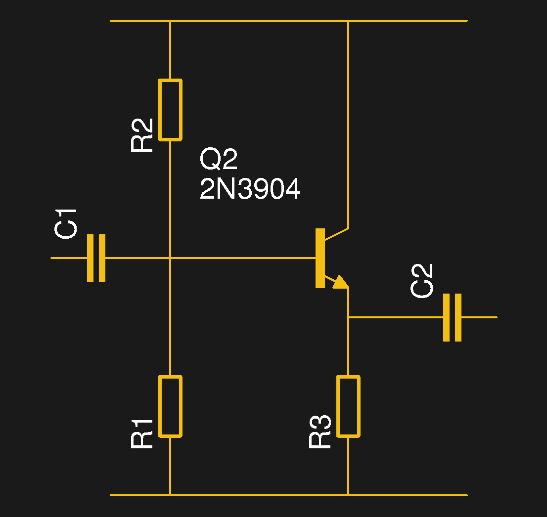
Just as the common emitter amplifier and common base amplifier each tied those respective transistor terminals to a fixed potential and used the other two terminals as amplifier input and output, so does the common collector circuit. The base forms the input and its bias circuit is identical to that of the common emitter amplifier, but the rest of the circuit differs in that the collector is tied to the positive rail, the emitter forms the output, and there is a load resistor to ground in the emitter circuit.

As with both of the other configurations, the bias is set such that the transistor is turned on and passing a constant current that keeps it in its region of an almost linear relationship between small base current changes and larger collector current changes. With variation of the incoming signal and thus the  base current there is a corresponding change in the collector current dictated by the transistor’s gain, and thus an output voltage is generated across the emitter resistor. Unlike the common emitter amplifier this voltage increases or decreases in step with the input voltage, so the emitter follower is not an inverting amplifier.

Continue reading “Biasing That Transistor: The Emitter Follower”

Biasing That Transistor: The Common Base Amplifier

We’ve previously remarked upon a generation lucky enough to be well-versed in microcontrollers and computersised electronics through being brought up on the Arduino or the Raspberry Pi but unlucky enough to have missed out on basic electronics such as how to bias a transistor, and to address that gap we’ve taken a look at the basics of transistor biasing.

All the circuits we worked with in the previous article had the transistor’s emitter taken to ground, took their input from the base, and their output from the collector. This configuration, called a Common Emitter amplifier is probably the most common, but it is far from the only way to use a transistor. Once you have set up the bias voltage as we described to the point at which the transistor is in its linear region, there are several other ways in which the device can be used as an amplifier. The subject of this article is one of these configurations, so described because it takes the transistor’s base to the ground instead of the emitter, as a Common Base amplifier. Continue reading “Biasing That Transistor: The Common Base Amplifier”

Biasing That Transistor: The Common Emitter Amplifier

If you open up the perennial favourite electronics textbook The Art Of Electronics and turn to the section on transistors, you will see a little cartoon. A transistor is shown as a room in which “transistor man” stands watching a dial showing the base current, while adjusting a potentiometer that limits the collector current. If you apply a little more base current, he pushes up the collector a bit. If you wind back the base current, he drops it back. It’s a simple but effective way of explaining the basic operation of a transistor, but it stops short of some of the nuances of how a transistor works.

Of course the base-emitter junction is a diode and it is not a simple potentiometer that sits between collector and emitter. The “better” description of these aspects of the device fills the heads of first-year electronic engineering students until they never want to hear about an h-paramater or the Ebers-Moll model of transistor function again in their entire lives. Fortunately it is possible to work with transistors without such an in-depth understanding of their operation, but before selecting the components surrounding a device it is still necessary to go a little way beyond transistor man.

Continue reading “Biasing That Transistor: The Common Emitter Amplifier”