Vintage eight transistor stereo amplifier

Eight Transistor Stereo Amplifier From The Days Of Yore

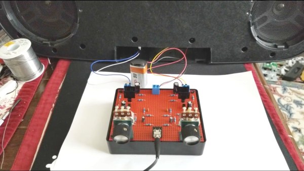
Reading an article about the first transistorized Hi-Fi amplifier, [Netzener] got the itch to make one. But what to use for the starting point? Enter an old Radio Shack P-Box stereo amplifier kit. After a few modernizations and tweaks, the result is an 8-transistor stereo amplifier that’s aesthetically pleasing, sounds great, and is fully documented.

The Radio Shack kit used germanium transistors, but with their high leakage current and low thermal conductivity, he decided to convert it to work with silicon transistors. He also made some improvements to the push-pull bias circuit and limited the high-frequency response. As for the finished product, in true [Netzener] style, he assembled it all to look like the original completed Radio Shack amplifier. He even wrote up a manual which you’d think, as we did at first, was the original one, giving that old, comfortable feeling of reading quality Radio Shack documentation.

Check out the video below where he uses a 9 V battery and half a watt per channel to fill a room with clear, stereo sound.

This isn’t the first Radio Shack kit that [Netzener] has adapted. Check out his single tube radio and classic neon “Goofy Light” box.

Continue reading “Eight Transistor Stereo Amplifier From The Days Of Yore”

Biasing That Transistor: The Common Emitter Amplifier

If you open up the perennial favourite electronics textbook The Art Of Electronics and turn to the section on transistors, you will see a little cartoon. A transistor is shown as a room in which “transistor man” stands watching a dial showing the base current, while adjusting a potentiometer that limits the collector current. If you apply a little more base current, he pushes up the collector a bit. If you wind back the base current, he drops it back. It’s a simple but effective way of explaining the basic operation of a transistor, but it stops short of some of the nuances of how a transistor works.

Of course the base-emitter junction is a diode and it is not a simple potentiometer that sits between collector and emitter. The “better” description of these aspects of the device fills the heads of first-year electronic engineering students until they never want to hear about an h-paramater or the Ebers-Moll model of transistor function again in their entire lives. Fortunately it is possible to work with transistors without such an in-depth understanding of their operation, but before selecting the components surrounding a device it is still necessary to go a little way beyond transistor man.

Continue reading “Biasing That Transistor: The Common Emitter Amplifier”