When a new piece of technology comes out, the price is generally so high that it keeps away everyone but the die hard early adopters. But with time the prices inch down enough that more people are willing to buy, which then drives the prices down even more, until eventually the economies of scale really kick in and the thing is so cheap that it’s almost an impulse buy. Linux SBCs, Blu-ray lasers, 3D printers; you name it and the hacker community has probably benefited from the fact that it’s not just the hacker community that’s interested anymore.
Which is exactly what’s started to happen with laser rangefinders. Once almost exclusively a military technology, you can now pick a basic “laser tape measure” for less than $40 USD from the normal overseas suppliers. Unfortunately, as [iliasam] found, they aren’t particularly well suited other tasks. For one there’s no official way of getting the data out of the thing, but the other problem is that the sample rate is less than one per second. Believing the hardware itself was promising enough, he set out to reverse engineer and replace the firmware running on one of these cheap laser rangefinders (Google Translate from Russian).
 His blog post is an absolute wealth of information on how these devices operate, and a must read for anyone interested in reverse engineering. But the short version is that he figured out a way to reprogram the STM32F100C8T6 microcontroller used in the device, and develop his own firmware that addresses the usability concerns of this otherwise very promising gadget.
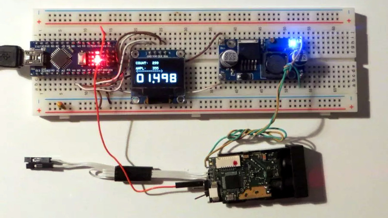
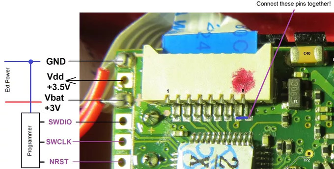
With some minor hoop jumping, the laser tape measure PCB can be hooked up to an ST-Link programmer, and the firmware provided by [iliasam] can be used to enable an easy to use serial interface. Perfect for pairing with an Arduino or Raspberry Pi to get fast and accurate range data without breaking the bank.
It probably won’t surprise you to see this isn’t the first time [iliasam] has gotten down and dirty with a laser rangefinder. This extremely impressive build from last year allowed for incredibly accurate 3D scans of his room, and before that he created his own rangefinder from scratch.


Wow! Quick, concise video! (Maybe a bit too quick for me B^)
I would like to see the LCD re-purposed in this hack, but maybe it is too confined to be of much use.
Great sleuthing and hacking. It was a bit confusing to read the (very good) Google translation and encounter the term “roulette”, which I eventually assumed was meant to be “ruler”. Maybe ‘линейка’ would have been clearer.
Well, you know how Russians are with their roulette!
B^)
From the translation page;;;
a small speaker (it constantly squeaked at work, so later I drank it)
B^)
“On the small headscarf there is an avalanche photodiode”
Headscarf, there, that is another name we can allocate to a new daughterboard for a new development system.
It will fit right in with “hat”, “shield”, “cape”, “wing?” as “something that is worn”.
“Headscarf, there, that is another name we can allocate to a new daughterboard ”
Or in this case, ‘babushka’.
Ohhh!
I’d thought babushka meant grandmother… because they always wore them, right?
So, instead of daughterboard, it is grandmotherboard!
B^)
What kind of update rate can I get from these systems? is 500 Hz posible with 100 um resolution?
That would be a hard negative. These are WAY too low tech for that. You’d need a much better TOF setup at several figures more. Why not use linear encoders?
I’m always on the lookout for position sensors for loudspeaker cones to close the loop. Optical systems are particularly attractive as I can sense position in multiple places.
Hmm. That’s an interesting challenge. Have you considered using laser reflection projection and machine vision?
Very hard to get low enough latancy and update rate with a scheme based on machine vision!
My current thoughts are to use metal cone drivers and capacitive sensing. Set the whole cone to the negative potential and measure the capacitance from probes close to the cone excited with a high frequency potential and gaurded. Using multiple probes to improve SNR and accuracy mainly rather than aiming to provide usefull feedback beyond the pistonic region.
Ha! Jesus I wish. Hopefully that kind of tech will trickle down someday but i don’t think you’re going to get anything even close to that cobbled together out of e-waste and an Arduino. Not using a laser rangefinder at any rate.
I can see pairing this with a set of binoculars, GPS module, digital compass, and a bit of trig to get a point-and-click geofence/waypoint device. Could be useful for scouting wilderness locations and/or drone reconnaissance…
…of course now I see the one he used is limited to 50m. Maybe something similar can be done with one of the 1000m units?
Already working on something like that. Has other more…shenanigans applications too
Neat design and info in the video. Was wondering if like with the composite style cheap IR thermometer used to make a thermal image… if this can be used in the same way to make a 3D scanner or more detailed depth information of an image. Maybe mounting on a turret or tracker also for easier scanning to make the image/scan faster.
makes you wonder why the original manufacturer didn’t spend a bit more time on software in the first place..
I think the term is Minimum Viable Product.
Uh because it’s in the impulse buy section of harbor freight? You gotta keep your expectations realistic here.
Hi. I am the author of this project.
I’m still experimenting with that laser tape measure and I can get 630 Hz measurement rate in my last experiment (maximum distance is limited by 6 m).
With a such measurement speed it is possible to make a cheap Lidar from this laser tape.
Does this interest anyone?
Um… yes?
@iliasam Do you know any of these that really can measure up to 50m/100m?
@Lúcio Corrêa I have seen 40m readings at my “X-40” laser tape when I was testing original firmware, but the measurement time was very long – more than 5 seconds.
What kind of precision can you get? whats the noise like?
Measurement accuracy significantly depend on signal amplitude. Noise can change from 1 mm to 30 mm in the worst cases.
White wall at the distance 2 m gives 1-2 mm distance measurement noise.
Certainly
You can pick that laser modules on usual chinese sites for like 17$ and they output serial data right away
Can you give a link?
All of the modules that I know and which are possible to send data to the UART, costs > 35$.
Cool and interesting read :)
Very cool article Tom! When you get tired of using this IR LASER hack for just distance measurements, you can try using the built-in IR LASER for upgrading your night vision goggles. From cheap toys to full scale NVG that only have a few feet range, you can add binoculars or a telescope to increase distance viewing. All you need is a diverged (wide) beam IR LASER to illuminate the distant target. This range finder could do that too (I think). Or you could pay $60 USD and buy one of these https://www.buynightbright.com.
————————————–
————————————–
I thought of something similar to this idea. In mine you would not need GPS but a good map, hall effect digital (or any) magnetic compass, and some Cartesian-to-Polar conversion trig (math). You would just use your binos’ cross-hairs to line up two or more KNOWN distant targets (waypoints) like mountain peaks or tops of skyscrapers. You already know their lat-long coordinates by plotting them before the journey and which side of the targets (N,E,S,W) you are on by the sun angle (or your compass). All you need is the magnetic compass degrees to the targets (i.e. bearing) and a SmartPhone, notebook, tablet, or a portable Arduino with monitor/keyboard could do the reverse math to find the distance along that bearing line from one of the known targets. (The known baseline is between the 2 known waypoints (in meters). The sides of this obtuse-triangle to you are the 2 magnetic bearings to the waypoints in degrees that forms the 3 corners – in degrees – the reverse of those bearings are the bearings back to you. Either side is now your distance in meters to either waypoint. Now automate that trig function and plot your location on a map w/o GPS.)
You only need to select the names of your two targets, your magnetic bearing to both, and which way is North from where you are. Which side of the targets you are is probably moot from the 3 magnetic compass bearings. It could be solved with math. You are just reverse-triangulating your position on a map from 2 known targets. Output would be: You are 20.5-miles 180° S from Waypoint Alpha Of course that would be instantaneous if all of this was automated with a hall effect compass, trigger button, and a computing device attached.