Our open source community invites anyone with an idea to build upon the works of those who came before. Many of us have encountered a need to control linear motion and adapted an inexpensive hobby servo for the task. [Michael Graham] evaluated existing designs and believed he has ideas to advance the state of the art. Our Hackaday Prize judges agreed, placing his 3D Printed Servo Linear Actuator as one of twenty winners of our Robotics Module Challenge.
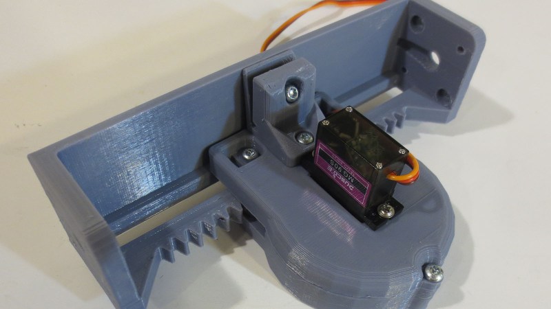
[Michael]’s actuator follows in the footstep of other designs based on a rack-and-pinion gear such as this one featured on these pages, but he approached the design problem from the perspective of a mechanical engineer. The design incorporated several compliant features to be tolerant of variances between 3D printers (and slicer, and filament, etc.) Improving the odds of a successful print and therefore successful projects. Beginners learning to design for 3D printing (and even some veterans) would find his design tips document well worth the few minutes of reading time.
 Another useful feature of his actuator design is the 20mm x 20mm screw mounting system. Visible on either end of the output slider, it allows mixing and matching from a set of accessories to be bolted on this actuator. He is already off and running down this path and is facing the challenge of having too many things to share while keeping them all organized and usable by everyone.
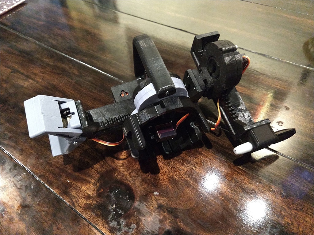
The flexible construction system allows him to realize different ideas within the modular system. He brought one item (a variant of his Mug-O-Matic) to the Hackaday + Tindie Meetup at Bay Area Maker Faire, and we’re sure there will be more. And given the thoughtful design and extensive documentation of his project, we expect to see his linear servos adopted by others and appear in other contexts as well.
This isn’t the only linear actuator we’ve come across. It isn’t even the only winning linear actuator of our Robotics Module Challenge, but the other one is focused on meeting different constraints like compactness. They are different tools for different needs – and all worthy additions to our toolbox of mechanical solutions.


This reminds me of an idea I had the other day.
Take a sheet of metal and cut an even ribbon, and then wrap it around a mandril to form a tight spiral. Then stretch the spiral to space it apart, and you have a quick cheap makeshift leadscrew for applications that don’t require great precision.
And another thing I tested out was a rack and pinion system made out of threaded rod.
I turned a small thick bushing out of aluminium and cut a groove in the middle, and then put a rod through it and ran it up and down the threaded rod, pushing it hard until the aluminium formed in the shape of the threads and made a perfectly matching pinion gear.
https://dumpt.com/img/viewer.php?file=lov82g4vhvqy90qknx0k.jpg
The idea being, that you can turn either the rod or the pinion. The test was part of a small lathe, where you may move the carriage by turning the pinion, or the threaded rod by the lathe’s own motor, by locking the pinion gear. Works both ways. The pinion gear also works as a coarse adjustment while turning the rod works for fine adjustment.
It failed because the lathe and therefore the motor was too small for the friction in the system and stalled. I didn’t get to test whether the pinion gear would wear out in use.
The theory was that the gear gets the right number of teeth at the right radius because the threaded rod only meshes with the gear evenly at a certain radius, and otherwise it pushes and grinds the aluminium away, work-hardening the metal at the same time. You just need to press it really hard and roll it along. Alternatively, you could cut slots in the threaded rod and turn it with a drill like a makeshift thread tap, and the gear turns along while the teeth get cut.
Umm. yeah. Way to hijack the comments, dude.
Don’t see much other commentary going on, so might as well.
So sharing one‘s thoughts is considered highjacking now? Come on…
Braze that spiral together and you’d have a version of how they made large-bore gun barrels back in the nineteenth century. Well, the cheaper shotguns at least. I think at least some rifles were attempted by spacing out the spiral ribbon, then brazing another around it to hold the groove.
Rifle barrels were usually made by taking a single long strip of steel and folding it round lenghtwise with a single seam going along the barrel, forge-welded against a spike inside the barrel, and then finally bored straight and broached to make the rifling. I don’t think brazed barrels would have held.
The rifling groove doesn’t make many turns inside the barrel, often less than one turn so keeping it together for brazing or welding would have been quite difficult.
This was great to see in person at the BAMF meetup! The Mug-O-Matic was a pretty slick piece of hardware.
The meetup was great, I will be doing that again, and thanks for the recognition! I’ve got a lot done but there is still a lot left to do to bring a TOY up to a competitive level of quality in a contest with serious high tech projects, lol, I’m gonna try anyway!