Current limited power supplies are a ubiquitous feature of the bench, and have no doubt helped prevent many calamities and much magic smoke being released from pieces of electronics. But for all their usefulness they are a crude tool that has a current resolution in the range of amps rather than single digit milliamps or microamps.
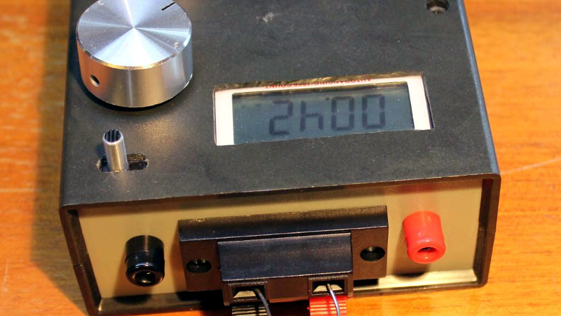
To address this issue, [Yann Guidon] has produced a precision current source, a device designed to reliably inject tiny currents. And in a refreshing twist, it has an extremely simple circuit in the form of a couple of PNP transistors. It has a range from 20 mA to 5 µA which is set and fine-tuned by a pair of pots, and it has a front-panel ammeter hacked from a surplus pocket multimeter, allowing the current to be monitored. Being powered by its own internal battery (and a separate battery for the ammeter) it is not tied to the same ground as the circuit into which its current is being fed.
[Yann] is a prolific builder whose work has featured here more than once. Take a look at his rubidium reference and his discrete component clocks, for example, and his portable LED flash.


Does this really work that well with unmatched and not thermally coupled transistors?
I would’ve used something like a BCM857BS.
https://www.nexperia.com/products/bipolar-transistors/general-purpose-bipolar-transistors/matched-pair-transistors/BCM857BS.html
Well,
1) it’s not THAT critical since you have a direct feedback with the LCD ammeter
2) the pots are less precise (and they seem to be sensitive to vibrations or motion)
3) there is not much current flowing, so not much heat-related drift, and the transistors are located close to each other.
I can reach a good tuning precision but the pots do all the drift… Still it’s very good when I need to develop current mirrors or differential amplifiers :-) A matched pair would be required for a more stringent and more expensive lab tool. Here the parts cost was mostly the knobs, as I bought them new, the rest comes from the random parts bin :-D
“But for all their usefulness they are a crude tool that has a current resolution in the range of amps rather than single digit milliamps or microamps.”
Most modern bench supplies have a high enough resolution, without spending much. Heck, even on my crappy home made analog supply i could get fractions of mA on a 5A range using 2 pots.
Now on the circuit …. i highly call that precision. there is literally no precise element in the circuit.
I can display “42” or any other number below 2000 so it’s “precision” enough, much better than my analog lab PSU that struggle on their lowest range (I sometimes measure a current that differs from the front panel display). So for me, yes, this is “precision” :-)
There are power supplies with a lot of resolution but their price is orders of magnitude more than what I’ve spent on this little hack :-)
Well, if we are talking about “precision” and not precision….
or “accuracy”
or “resolution” :-)
yes, it’s all context-dependent…
I appreciate simplicity; I appreciate a good junkbox build. But I’ve really gotten tired of the whole coarse/fine dual pot thing. We have some very expensive power supplies at work, yet the manufacturer chose to cheap out and use two pots for voltage and current limit.
Ten turn potentiometers are a FRACTION of the cost that they used to be. About $2 each if you buy 5 or 10 at a time.
How constant is the output over what voltage range?
yeah but try quickly going to full scale from zero with a 10 turn pot.
Is that really a factor? If I need a step change in current, I’d install two 10 turn pots and a switch to flip between them.
“I’d install two 10 turn pots”
so we’re back to the initial problem :-D
I don’t have the mentioned multiturn pot. I have some multiturn adjustable resistors but they are not suitable for front panel use. I also side with mime about speed :)
As for constance : I can tune to 1mA across a 10K pot and measure from 0V to 8V. I should check with other currents though, but that requires different pots :-)
Sure, but single turn potentiometers are also cheaper. I would say 2 are still cheaper than am multi-turn. Yes, I too would prefer a multiturn, but they are not always the best solution.
I’m expressing my preference. I would rather use a 10 turn pot than two pots. One less knob, inexpensive 10 turn pot, not sure the difference in price is significant.
The nice thing about these sorts of crude circuits is you can swap any part at will, be it the potentiometers, the transistors, etc…
Yes, exactly. My comments were in no way meant as a criticism.
Noob question: Since it is powered by a 9V, I assume max V to be <= the battery voltage (or maybe strictly < Vbat due to voltage drop across T1?).
What is the lowest voltage this device can supply? I suppose that probably doesn't matter since the purpose is current limiting and the voltage will be the max (up to the limit asked about above) required to deliver the desired current.
You know the U=R×I law, the rest follows.
https://cdn.hackaday.io/images/162931531433094650.png shows the principle : the max voltage is determined by the battery, minus the drop across R3+R4+R5, which is held at 0.6V by the feedback transistor T2.
When saturated, the drop across T1 is not significant.
In practice, that would be (a bit more than) 8V, which is ok since I don’t think I’ll exceed 5 or 6V.
There is no real minimal voltage, since T1 will adjust the output voltage, up to its maximum rated Vce.
Neither transistor should be in saturation. The gain drops significantly at saturation.
I would expect to lose two diode drops plus a bit more. The Vbe of each transistor. Current regulation would be expected to suffer a bit as you approach two diode drops below the battery voltage. Whether or not that is significant depends on your needs.
In any case, if more headroom is needed, a second battery could be added in series as long as the transistor’s rating is high enough.
I’ll have to measure at various currents to confirm everything but it seems that at low currents, it’s close to 0.6V and not two diode drops.
But since I need to go up to maybe 6V max, I have enough headroom with one 9V battery :-)