If you haven’t noticed, CRTs are getting hard to find. You can’t get them in Goodwill, because thrift stores don’t take giant tube TVs anymore. You can’t find them on the curb set out for the trash man, because they won’t pick them up. It’s hard to find them on eBay, because no one wants to ship them. That’s a shame, because the best way to enjoy old retrocomputers and game systems is with a CRT with RGB input. If you don’t already have one, the best you can hope for is an old CRT with a composite input.
But there’s a way. [The 8-Bit Guy] just opened up late 90s CRT TV and modded it to accept RGB input. That’s a monitor for your Apple, your Commodore, and a much better display for your Sega Genesis.
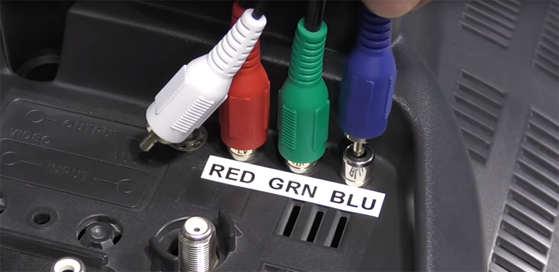
There are a few things to know before cracking open an old CRT and messing with the circuits. Every (color) CRT has three electron guns, one each for red, green, and blue. These require high voltage, and in CRTs with RGB inputs you’re looking at a circuit path that takes those inputs, amplifies them, and sends them to the gun. If the TV only has a composite input, there’s a bit of circuitry that takes that composite signal apart and sends it to the guns. In [8-bit guy]’s TV — and just about every CRT TV you would find from the mid to late 90s — there’s a ‘Jungle IC’ that handles this conversion, and most of the time there’s RGB inputs meant for the on-screen display. By simply tapping into those inputs, you can add RGB inputs with fancy-schmancy RCA jacks on the back.
While the actual process of adding RGB inputs to a late 90’s CRT will be slightly different for each individual make and model, the process is pretty much the same. It’s really just a little bit of soldering and then sitting back and playing with old computers that are finally displaying the right colors on a proper screen.


There is a follow-up video that includes using the same TV for VGA via a converter cable and some dos drivers so the VGA card will output the correct frequency for an NTSC TV.
https://www.youtube.com/watch?v=NkpSBK3g-gA
I been thinking on modding a TV like this for my Amiga.
Don’t try this if your TV is a “hot chassis” one, typically if its original power cord has only two circuits (no ground lead). You don’t want to expose signals nor ground from within a hot chassis appliance at an external connector, you can get electric shock, even get killed!
Beat me to it!
Just to reduce the chance your comment is overlooked, here it is again:
“Don’t try this if your TV is a “hot chassis” one, typically if its original power cord has only two circuits (no ground lead). You don’t want to expose signals nor ground from within a hot chassis appliance at an external connector, you can get electric shock, even get killed!”
For those that still didn’t get it…
“Don’t try this if your TV is a “hot chassis” one, typically if its original power cord has only two circuits (no ground lead). You don’t want to expose signals nor ground from within a hot chassis appliance at an external connector, you can get electric shock, even get killed!”
B^)
I second, third, fourth you on this. I will emphasize with capital letters :
“DON’T TRY THIS IF YOUR TV IS A “HOT CHASSIS” ONE, TYPICALLY IF ITS ORIGINAL POWER CORD HAS ONLY TWO CIRCUITS (NO GROUND LEAD). YOU DON’T WANT TO EXPOSE SIGNALS NOR GROUND FROM WITHIN A HOT CHASSIS APPLIANCE AT AN EXTERNAL CONNECTOR, YOU CAN GET ELECTRIC SHOCK, EVEN GET KILLED!”
TL;DR: If there’s no 3rd pin on the wall plug, for Heaven’s sake DON’T DO IT!
For those reading this in a mirror:
“!DELLIK TEG NEVE ,KCOHS CIRTCELE TEG NAC UOY ,ROTCENNOC LANRETXE NA TA ECNAILPPA SISSAHC TOH A NIHTIW MORF DNUORG RON SLANGIS ESOPXE OT TNAW T’NOD UOY .)DAEL DNUORG ON( STIUCRIC OWT YLNO SAH DROC REWOP LANIGIRO STI FI YLLACIPYT ,ENO ”SISSAHC TOH“ A SI VT RUOY FI SIHT YRT T’NOD”
Friend had one of those Chipboard Box Tv’s years ago hooking up a VCR Got locked onto a BNC cable for a second i think he kicked me off of it was like time froze.
A hot chassis TV will have two prongs, but a two prong TV may not be hot chassis. I’m sure CRT TVs with grounded plugs existed, but I don’t think I ever saw one; even my early-2000s CRT HDTV had a two prong plug.
I would guess the set of TVs with hot chassis and the set of TVs with “jungle chips” overlaps very little.
Ok, great. One person almost explains it and two people oh so helpfully copy-paste.
I can’t think of a single CRT TV that I have ever seen which had a third conductor for ground. I’ve seen that on more modern flat screens and maybe on really rear projection TVs but never on a plain old CRT. What are you smoking?
As far as I can tell that effectively makes your advice “don’t do this at all”. If one doesn’t know for sure that they can do this safely that might just be good advice but if someone really wants to do this might be hard advice to take.
Further down I see someone commenting that not all 2-prong CRT TVs were hot chassis. Great! So.. next obvious question is how to tell the difference. Is it as simple as testing for continuity between the neutral and the outer shell of the F-connector or some other connector? If so then that would certainly beat going on a wild goose chase for an old 3-conductor CRT television!
So, what if all one can find are hot-chassis TVs? Is it hard to mod one to not be hot chassis? I remember reading guides for doing this with Antique radios. It typically involved just cutting a wire that connected to the chassis and then moving a few other connections around and adding a fuse. I don’t really remember the details except that it wasn’t anything difficult. Maybe these TVs with the connections hidden among layers of PCB would be harder to mod in that fashion though.
Second idea… an isolation transformer. You could just plug the TV into an external isolation transformer. That would take care of the problem. Just make sure it’s a true isolation transformer, not an autoformer. Also don’t plug anything else into it! The only problem with this is it would be easy for someone who doesn’t know any better to unplug it from the transformer and instead plug it directly into the wall.
That could be solved by mounting the isolation transformer internally to the TV. Just cut the power wire where it enters the case and patch the transformer in there.
Power isolation transformers are kind of bulky and expensive though. What else can we do… well, so long as we are talking transformers why not just use small, signal level isolation transformers on the 3 inputs? Really, why not? That should be EASY.
Can you send baseband video through a small transformer like that? Is the signal going to make it through? Also where does the sync come from? Mixed in with green? Would that not already have been separated off by this stage in the TV’s circuitry? So the TV’s teletext, OSD etc will be generated with the same mutual sync.
The problem here is that this is HackaDay and there are people here from all over the world so standards differ.
So some basics (I am in Australia where we have PAL instead of NTSC).
Two pin plug – most likely means the device is “double insulated”. The requirements here is that there be no conductive path from inside the device to outside the device. This is one layer of insulation. The other layer of insulation was often done with a step down transformer. This has nothing to do with hot chassis but most (and not all) hot chassis TV’s had two pin plugs so is not a safe indicator of “hot chassis”.
Hot chassis TV’s were a mixed bunch. In lower voltage areas (90v to 120v) the mains was rectified and the negative side of the rectifier was connected to the chassis. This is what made the chassis “hot”. Later when TV manufacture was more international we had sets that were designed to be lower voltage released into other countries. Often a internal stepdown transformer was used in a set that was originally designed to be hot chassis.
A problem that arose with hot chassis is the internal ground reference was live so it couldn’t come out of the TV for input connectors. This was overcome by inserting a 1 to 1 balun between an antenna input and the circuitry for isolation. This is NOT the 75ohm to 300ohm balun that some TV’s had but a separate ballun. Hot chassis TV’s generally only had an antenna input.
So to answer one question here – yes you could use baluns for the RGB inputs for the color and croma information but you would loose sync because sync is too low in frequency to pass through a balun very well.
The isolation transformer is the best “fix” for a hot chassis.
The chances of finding a set that is so old that it would be hot chassis are very slim now. To give an idea – MOST (but not all) hot chassis TV’s were in the era when the case was a wooden or ply box rather than plastic.
Any TV with a composite input should be safe, otherwise that input would have the same problem.
The number of wires in the power cord has nothing to do with whether the TV uses a transformer in its power supply to isolate the internal circuits from the line.
Measure the resistance from the circuit ground to the pins on the power cord. If it’s near zero, you have a hot chassis set that shouldn’t be used for a mod like this.
A TV in a plastic case is likely (pretty much certainly) double-insulated, rather than earthed-case. Particularly since you can’t earth plastic. In that case, the safety regulations I’m aware of (but probably the same across most of the world, and probably as well-observed in a particular country as any of that country’s other consumer-protection laws) would require any metal bits to be safe to touch. So, as you say, Bill. Should be fine.
Didn’t “hot chassis” go away about the same time they stopped using thermionic valves to work televisions? Like, 50 or 60 years ago?
Plenty of plastic-cased devices in the UK, where we have very good electrical safety standards, use a solid plastic earth pin. Because there’s no earth in the device. Because it’s got a plastic case, with plastic-insulated wires inside. There’s nothing to usefully attach earth to.
I would imagine that even in bits of the USA that have finally got round to using 3 pins (and, whoa!, distinguishing them so you can’t swap live and neutral (dude it’s the 21st flipping century! I mean not even that, it’s, what, post-1950! A time when we no longer plug the electric clothes iron into the light bulb holder. Gruß Gott! Really, men on the Moon, international computer network, mobile satellite phones! But still hilarious live / neutral mixups in big countries!
Where was I? Anyway, yeah. What a state! I can imagine this slipping Edison’s mind, he was probably busy stealing one guy’s ideas when he should’ve been stealing somebody else’s, but give it a century and then some, and still !
I mean here I am, italicising across the world, and there’s people probably electrocuting themselves through the world’s stupidest Victorian mains plug standards. And you can’t blame the Victorians for expecting us to have built upon their work by now!
Quote: [Bill] “Measure the resistance from the circuit ground to the pins on the power cord. If it’s near zero, you have a hot chassis set that shouldn’t be used for a mod like this.”
This is not true and a dangerous assumption. Many hot chassis TV’s had the chassis connected to the negative of rectified mains voltage so you would see a diode and not near zero ohms.
TV already has chinch composite video input, exposing both ground and signal patch – your comment makes no sense
You know you’re getting old when people start waxing nostalgic for the stuff you couldn’t wait to get rid of for better stuff.
Very true. I had a similar TV as a student and I modded it to have a headphone output. unfortunately the switch for this went intermittent after some time. But several years ago I got rid of the TV – in the meantime unused for a decade or so. Unfortunately I did not think of a mod for RGB in. That would have been very nice, as I used it mostly with the C64.
Probably this TV could have been operated as “hot chassis” in countries with extra low mains voltage or derived from such a construction. It used a strange design: A big transformer from 230V to 120VAC and after the rectifier a big linear regulator to something like 140VDC. Even the tiny 0,2W speaker amplifier was operated from 140V with an audio output transformer. Then most other voltages were derived from the line output transformer.
For me this looks like a converted design for 120V direct mains operation.
Unless there was a connection from the power line to the chassis that came before that big transformer the transformer should have isolated the chassis for you.
That sounds very weird! This was a valve / tube TV right? Technically way back then it’d have been 240V or 220V. Not that it really made any difference. Long-story-short, when it came to “unify” Europe’s voltages, it was done only on paper. They settled on 230V as a nice compromise, but called it 230V with some allowable deviation, taking in both, but reining it in a bit round the edges. Now the acceptable limits are 216 – 253 volts coming from a European socket, and by an odd coincidence the British ones tend more toward the high end than the Continental ones. By about 10V each way.
Actually at that sort of voltage accuracy doesn’t matter so much, everything is built to allow for a bit of variation. If it’s driving low-voltage DC, there’s a regulator circuit it it’s needed. If it’s a toaster, they just make the wire a bit thicker and allow for a bit of variation in toasting time.
Anyway… I write to ask, how do you do a 140V audio amp? Is this with valves too? I’m aware of them working around 60V – 90V, not so high as 140V. Although I’m also aware they did some somewhat funky things with circuit design to keep component count down, so maybe the valve saw 90V and the other 50V went somewhere or other. Still 0.2W at 140V. That’s 1.4mA, it’s just the wrong way round! Just seems weird these days. Back then, sure, voltages could be all over the place in the early days, and transformers equally profuse. There were also high-impedance speakers, especially for driving from amps like that. Or perhaps not quite like that, but still on valve-ish principles, high voltage low current.
The primary voltage rail of most TV’s was in the range of 90v to 180v. The set you mentioned was designed for 110v to 120v and they just added the step down transformer for 240v areas. Later sets had a duel primary transformer where the primaries were paralleled for 120v and series for 240v.
Now … the weirdest set I saw was a specific model of Telefunken (multi-standard). It was a switch mode power supply that was a repair nightmare.
The same transistor was used to drive both the flyback transformer (LOPT) and the switch mode power supply transformer. The switch mode chopped at about 200kHz and of course the Flyback chopped at about 16 kHz. The two chop frequencies were modulated together to drive the transistor and the output went thought LC networks to separate the drive to the transformers.
Don’t even ask about the horizontal deflection circuitry.
Still want to get rid of, even now; and my back thanks me for the effort.
Looks like that the TV set modded was the US version of an European one with SCAR connector. If you look the back panel there is a cutout in the shape of a SCART connector and on the PCB the composite in and audio in jack are mounted on a plastic box sized like a SCART socket.
See the same on heaps of old cheap TVs here too, was hopeful when I saw one that the board would be the same with a different socket but that wasnt the case, just the 2 crappy RCA sockets and the scart hole thing was just there to I assume let them not have to make a second large mold to make the cases.
HAD editors, stop using the term circuit bending.
The 8-bit guy knew what he was doing. Circuit bending is randomly connecting signals in a circuit. It’s a technique for clueless idiots, nothing hackery or article worthy about it.
YES.
This is circuit bending:
https://www.youtube.com/watch?v=MmiBhLUkKEM
YES.
Back in the day, when people used to adapt the things they had into the things they wanted, using their own ingenuity and whatever tools to hand, we called it “hacking”. At one point it got quite popular.
Not the same meaning as that other kind of “hacking”, though. No, people confusing the two used to really piss us off, actually. I dunno if it was the laziness or the hyperbole that mostly bothered us. Then if the journalist in question was a really contemptuous lazy bastard he’d try and pass it off as some sort of deliberate trick. Nobody ever fell for that, like.
is it a real hack a day post if nobody complains to the editors?
Just to pick nits…”Every (color) CRT has three electron guns, one each for red, green, and blue. These require high voltage….”. Yes, but don’t imply that monochrome monitors don’t have lethal voltages. They may not be as high, but still high enough to be verybcareful.
Just to pick the nits off your nits, you’re confusing positive and negative implication. Necessary vs not necessary, absence of evidence vs evidence of absence. When mis-used deliberately this can be the worst kind of “playing dumb”. In this case, though, it probably just wasn’t necessary to warn people that electron guns use thousands of volts. There ought to be a sticker on the CRT for one thing, and probably one or two on the outside of the case.
Also high-voltage capacitors can hold a dangerous charge for a while, and there’s no obvious way of knowing which ones are those.
And mains voltage alone can be quite deadly. Look both ways before you cross the road. And don’t imply you don’t need to keep looking, once you’ve started crossing.
| Every (color) CRT has three electron guns, one each for red, green, and blue.
Nope. Trinitron tubes use one electron gun.
As I understand it, (AIUI), Trinitrons have one CRT heater, which heats 3 individual cathodes.
Yup, three guns side by side, rather than arranged in a triangle.
https://youtu.be/0aFhzGEBQlk
[youtube https://www.youtube.com/watch?v=0aFhzGEBQlk&w=560&h=315%5D
be careful around high voltage! just because the tech is getting older doesn’t mean crt tvs aren’t still dangerous!
If the tech wasn’t careful he or she wouldn’t get any older!
Why would anyone think otherwise? Things get safer as they get older!?
My second computer that I made was a 6809-based Forth computer. I designed a lovely 4-bit per channel palette RAM and DAC (ok, a bunch of resistors) output, and then set about the TV. This was before SCART, but the Grundig TV I had (yes, isolated power supply etc) had a TDA3561 PAL decoder in it – a very common chip family for PAL TVs, that also happened to have an RGB interface for Teletext boards to be added in. A bit of ribbon cable later, and we had colour on the screen. Though Teletext was only eight colours, the interface was analogue so I could squeeze it up to 4096 colours.
The TV, its TDA3561 decoder and the ribbon cable are all now long, long gone but I still have the clock/palette/DAC board in my little museum.
Nice! How many colours on screen though? 8-bitters generally kept 16 or less, because that’s around the limit you can shift data round enough to do anything useful with in real time, like games. Of course 4096 colours from the DAC doesn’t mean you need a lot of bit depth for the screen.
There’s tricks like reloading stuff per scanline. That’d be something nice to fit into your video circuit. Interrupt the CPU, through a flipflop to enable, perhaps right at the end of the scanline once the last pixel has clocked out. Or (or, as well!) have that same line slip off to a circuit that can load values from a table. Perhaps a table including address and data. So each scanline you could update the CLUT (aka palette), or even the scanline address registers, to allow hard scrolling. Maybe mixed graphics modes.
Ah, that’s a job I’d love to have had, back when I was 2 or 3 years old, designing video systems for old home computers. There was a limited amount of hardware, with limitations on speed and cost, among others. But within those you could do ALL SORTS of things. And Atari did most of them!
Actually for my hypothetical graphics setup that’s probably what I would do. Just rip off the Atari 800 / 800XL series’ chips, ANTIC and GTIA. ANTIC had just a few opcodes, hardly any, but could do just about anything, including real text and graphics modes, all mixed on a per-scanline basis. Any colour depth / resolution / scrolling / RAM use. Simple and genius in both directions, all directions, at the same time! All relocatable, with perhaps limits on the lower few bits having to align on boundaries.
All set up in a “display list” that’s the program written for ANTIC in it’s own special machine code. All run in real-time as the pixels squirt out. Updatable and alterable whenever you like, every scanline or frame. Bloody genius!
And the 6502 CPU ran at twice the speed the C64’s did, even though the machine was a few years earlier!
And I haven’t mentioned the hardware sprites yet.
GENIUS! Still no need to explain it all here, there’s plenty online. Genius though! Great chip. Only a shame it cost far too much for anyone to actually buy! Atari missed a trick in not putting it in arcades, it would’ve wiped the floor with most arcade hardware up til the mid-1980s, when med-res and the first 16-bit CPUs appeared in arcade machines. By putting that in cabinets and allowing special ROM carts (or even cassettes, which would’ve made it the second arcade machine to take games on audio tape!), with some sort of anti-copy dongle… They’d have had arguably the best arcade graphics, cheap mass-production on an already-finished product, just in a new case.
Would’ve made adapting between home arcade games trivial, in both directions!
Actually Archer Maclean sold, in small numbers, his own arcade machine, “Dropzone”, that was an Atari 800XL in an arcade cabinet!
Hi Nick I know this was a few years back now, but I’m currently researching whether I can RGB Scart mod my ITT Trimline CT2512 which has a TDA3561 chip. I don’t suppose you might be able to help me?
FYI, CRT TV’s, especially big screen, often show up on Craigslist Free category.
Those big screen TVs are also a good source of front surface mirrors.
And a large Fresnel panel for solar experiments!
But what do you do with the rest of it?!?!
Chuck it in the river.
i thought circuit bending is shorting wires across the a/v chips to glitch them into making sounds.
yes, this is not circuit bending, this is just reverse engineering the composite video circuit, then engineering a clean way to hook it up.
i guess its a good thing that i still have my commodore 64 monitor. for many years it was my goto display for game consoles. (of course it was this was also when my parents thought i had nothing to use as a display, cause i wasn’t suppose to be gaming).
And being a C64, your GOTO display!
[….]
No, only joking. Everyone knows the C64 had a crap BASIC.
20K of ROM, and what did they put in there? Shopping lists!? If you wanted the sound, sprites, or any graphics at all, it was all POKE! No BASIC commands to use the hardware. For all the use BASIC was they may as well have just stuck a hex loader into 64 bytes, and used the rest of the space to include The Last Ninja.
Actually later Atari 8-bit models included Missile Command where they might’ve put some string handling routines. So it’s not such an unusual idea.
I remember reading about this hack a looooong time ago, so I was overjoyed when I saw it pop up on the 8-Bit Guy’s channel. My family had a couple TVs from the same product line… A 27″ and a 19″… Sadly, by the time I’d heard about feeding RGB video to them through the OSD circuit, they’d both given up the ghost. That 27″ would’ve made a bitchin’ arcade and retro console monitor! :(
Very late to party: a lot of the people warning far too much too avoid TVs with only 2 prongs on the power cable… do not know WTF they are talking about. One of the most popular and safe CRTs for RGB modding is anything with the Sony BA-5D chassis (early-mid ‘aughts’, believe they were made around 2000-2005). Those mods are incredibly well-documented (mostly by the fine folks over on Shmups), and they are but 2 simple prongs. TV’s aren’t as dangerous/lethal as a lot of people will lead others to believe, but precautions should be self explanatory / go without saying, anyway! :)