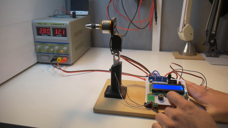
When designing model aircraft of any shape or size, it’s useful to know the performance you can expect from the components chosen. For motors and propellers, this can be difficult. It’s always best to test them in combination. However, with the numbers of propeller and motor combinations possible, such data can be tough to come by. [Nikus] decided it would be easier to just do the testing in-house, and built a rig to do so.
The key component in this build is the strain gauge, which comes already laced up with an Arduino-compatible analog-digital converter module. Sourced for under $10 from Banggood, we can’t help but think that we’ve got it easy in 2018. A sturdy frame secures motor and propeller combination to the strain gauge assembly. An ATMEGA328 handles sending commands to the motor controller, reading the strain gauge results, and spitting out data to the LCD.
It’s a cheap and effective build that solves a tricky problem and would be a useful addition to the workshop for any serious modeler. We’ve seen other approaches in this area too, for those eager to graph their motor performance data. Video after the break.
[Thanks to Baldpower for the tip!]


How about (semi-)automatic data aquisition? Graphs seem like a natural way to present data from such experiments.
Pick up the home version of labview and you can automate just about anything. Think it’s $50
I am pretty sure Python is more than enough for this task. However, I can’t see any interface that allows to connect this circuit to a computer.
You should be able to connect to the arduino via a standard USB-TTL adapter to get a serial output, but the data collection capacity of the Arduino is somewhat limited. I was working on solving this same issue for a side project of mine a few years ago, and I ended up going with the TivaC launchpad, as it’s fairly inexpensive and has better peripherals for data acquisition (higher resolution ADC, more timers, etc.)
You can read about the results of that project here: https://www.miniquadtestbench.com/equipment/
All the code is available, and the hardware is listed there if you’re interested in replicating it.
Well, it IS a computer for one thing. I’d guess that black connector would have something like serial port on it if for no other reason then to upload a program to it. A different choice of display would allow graphing without another computer anyway (and I’ve done some painful things with custom character sets on displays like the one shown, too, but I’d not wish that on anyone).
I want to believe this is a joke, but…
I’ve never had good experiences with labview. More often than not, a project could be simplified a lot by a quick Arduino sketch. This is a simplier application and could be done with a daq and a couple VIs, but I’d probably still use an Arduino.
If you want to do anything more complex like having a HMI you’re not going to have an easy time. I built a control system around LabView for my vacuum system. It handles automated pump down and venting reading analog pressure sensors and processing their signals, controlling pumps and valves via PCI relay card, serial interfaces on valves and other sensors, etc. All with a nice touch screen HMI showing the status of all pumps and valves as well as pressures.
I cant do that with an arduino. At $50 its worth to keep around and for stuff like this you have your graphing and can control everything from stop to start. Yeah, there is a bit of a steep learning curve.
Grab LogView it’s free and it can make nice graphs and data tables :)
It can use own open protocol which is pretty simple to use.
Nice project, and a dangerous wind blower loll
I’ve been working on something similar with an integrated wattmeter and laser taco, so you can create overlapping graphs for thrust Vs power Vs RPM for a said propeller.
This is an absolutely great build given that it’s all self-designed PCB and hand-soldered SMD – great work!
Having worked with load cells for a very long time, I’m curious how he calibrated the load cell/thrust output (maybe I missed something) – it looks like he’s just trusting the data sheet for information (the code has a suspiciously simple calibration factor in it). If it’s not calibrated, you’ll just have a relative value for thrust.
The simplest “good enough” calibration for this rig would be to orient the beam horizontally with the motor mount facing upward and then hang a series of known weights on it from the center of the motor mount.
Useful data is my favorite kind of data.
In current setup the load cell measures the torque, not the thrust. With fixed lever length converting one to the other is as simple as computing/measuring scaling factor, but the author just uses a “magic” value, most likely copied from the datasheet of the converter chip. This still will provide some useful information, just not expressed in any physical units.
Another thing that made me cringe are the 3-printed parts. The bottom part is printed with horizontal layers, and this is the direction in which the part is the weakest to the bending forces. The fillet at the bottom helps a little, but if I were designing the stand, I would extend the base towards the circuit board, and add a beam reinforcing the holder. The tiny screws don’t look strong either…
The setup may be fine for testing a small propeller, but when working with such parts it’s better to be safe than sorry. Having hand cut by a spinning propeller is vary painful, and such injuries do not heal quickly. Don’t ask me how I know it :)
For people who wants to build a thrust stand, I recommend this project. https://github.com/iforce2d/thrustTester
It use a neat graphical representation and you can even enter command line to semi automate the test. There is great video on the setup. https://www.youtube.com/watch?v=V3kxl4dHAwE
you didnt use weight so what did you do?