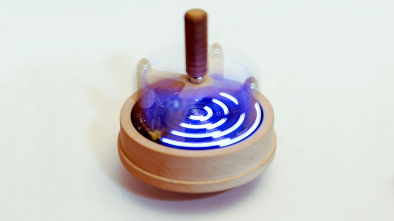
Sometimes a beautiful project is worth writing on that merit alone, but when it functions as designed,someone takes the time to create a thorough and beautiful landing page for their project, we get weak in the knees. We feel the need to grab the internet and point our finger for everyone to see. This is one of those projects that checks all our boxes. [Nathan Petersen] made a POV toy top called Razzler, jumping through every prototyping hoop along the way. The documentation he kept is what captured our hearts.
The project is a spinning top with an integrated persistence-of-vision (POV) display. That’s the line of LEDs that you see here. To sync up the patterns, the board includes an IMU, but detecting angular velocity with either gyroscope or accelerometer proved problematic. [Nathan’s] writeup of this is worth the read itself, but you’ll also enjoy the CNC workworking part of the project used to create the body of the spinning top.
This was [Nathan]’s first big solo project, and so many of the steps are explained by someone who just entered the deep-end very quickly. If you have experience, you may grin at the simplified reasonings, but for a novice, it makes for an approachable lesson. The way he selects hardware and firmware is pragmatic and perhaps even overkill, so you know he’s going into engineering. This overshot saved him when there were communication problems which needed a sacrifice of some processing power to run I2C on some GPIO.
We hope you enjoy reading about this combinations of POV, firmware (or is it?), and centrifugal force.


Very nice — and thank goodness, an ARM processor.
A handy little STM32F030 Cortex M0 at that!
Well done Nathan, while this MCU may be one of the ‘smaller’ ARM based MCU’s, with around 36 peripherals, 413 Registers, and 3000 Register Bitfields it is a complex and capable beast, a great challenge for a first MCU project!
Just reading the MCU documentation takes a serious effort :)
Cheers,
Terry
Funny that they used a clone of (I assume) a TLC5916, but went with a genuine STM32. There are also the GD32 pin-compatible clones of those.
Has anyone seen those in the wild? I think the Particle debugger uses a GD32F103.
For syncing up the patterns, a simple light sensor (phototransistor) might work. Most rooms will have varying brightness in different directions so one could easily detect the speed and orientation.
If you’re going to do that probably best to add a shroud so it’s own blinking LEDs don’t interfere with the timing. Although it’s not going to work well in a dark room. Maybe a weight sensor might be a good way to go and just calculate the speed from the g-force.
Maybe magnetometer or hall effect sensor measuring Earth magnetic field?
Something tells me that a zero force potentiometer + small weight on a springloaded arm would be the most realworldy solution to this.
Oh wow, on closer inspection that’s actually a lot larger than I originally thought.
An LSM3003C from ST is a combined magnetometer and accelerometer. And you can actually buy them.
we had to make a balanced PCB for a gyroscope and ill tell you something … balancing out a PCB and keeping it consistent over 100 units was a real chore
in the end i placed a bunch of those sparkfun solder jumpers on one side and used that to weight each one individually with 4 ‘mail’ scales, waiting for them to cool each time
So could this be made into a pov dreidel?