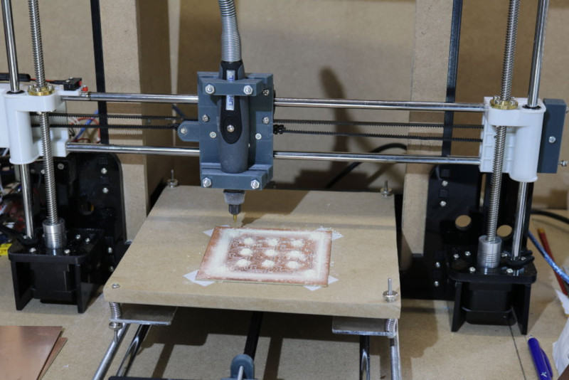
Got a 3D printer? With a bit of work, you may also have a PCB miller. That’s the basis of this neat hack by [Gosse Adema], who converted an Anet A8 3D printer into a PCB miller by building a holder for a Dremel rotary tool and adapting the GCode. This approach means that the adaptations to the printer are minimal: the only hardware is a 3D-printed holder for the Dremel that replaces the print head. The result is an impressive PCB milling machine that can do double-sided PCBs and make through holes.
The excellent write-up that [Gosse] did on this hack describes how he converted the printer, and how he took an EagleCAD design and converted it into four GCode files. That’s one for each side of the PCB, one for through holes and one for the final outline of the PCB. These are then fed to the 3D printer and cut in turn with an appropriate milling bit on the Dremel.
We’ve featured a few similar conversions before, such as this vintage conversion of a Makerbot and this cheap engraver conversion, but this one is much more detailed than those, covering the entire process from PCB design to final product.


Now days it makes no sense to make your own. Cheep chinese makes my prototypes for 2.00 for 10
Yes there is shipping so make sure you order enough to make shipping worth it.
And how long do you wait?
Wait time that is ok for you may not be ok for someone else.
Finishing the board design and having one in hand the same day is definitely a good feature regardless if it is your higher priority or not.
XY tables are really cheap these days…..
The point is making one. A completed PCB can be bought really cheaply as well. But, milling one oneself with the same machine that extrudes the enclosure for the resulting board is a rather complete solution. Additionally, it is educational–such is teaching CNC kinematics to someone formerly only familiar with 3d printing. I just did a similar project myself over the past two weekends, getting a Prusa Mendel i2 to mill plywood using a Dremel flex shaft. I had to design the flex shaft mount in openscad. I also wrote a bourne shell script to generate the gcode I needed. And I filled my living room with smoke in the process lol. It is an ongoing project–I would like to try milling a PCB.
Too funny, you had me chuckling with “filled my living room with smoke” … My kind of guy with the right priorities. Always find it interesting having to explain to others *the point* of hacking /making. It * IS NOT * always about the end goal and how cheaply something can be made from inexpensive components that get folks most of the way there. Some like to build from scratch others like to use “building blocks”. If you have to ask why no amount of explanation will clear it up.
XYZ, I mean.
Can you link to a good one? Many manual ones have significant backlash.
It would be interesting to learn what kind of tolerances it can hold. For PCBs its probably fine if you go slow enough. Rounding the corners in the g code would help too.
Thanks, wondering how to adapt a Wanhao – it’s a low end unit wildfires about aud$300 couple of years ago from Kogan/dick Smith…
Aargh, lol should be “..low end unit sold for about..” weird typo correct delays erratic so messy when typing fast, edit option on posts please 5 to 10min option, would help my handicapped friends heck of a lot too they wouldn’t be as dissuaded posting ?
If you’ve got the Wanhao i3 then that’s based on the Prusa i3 platform and should be a pretty similar mod to the one posted. Google is our friend
As far as 3D printers go, a wildfire might be exactly what you’re getting with a low-end unit. =)
Awesome gallery of Tilescape Gothic City 3D Terrain and Kickstarter link. https://www.facebook.com/100011672956856/posts/771419666590458/
Interesting! I’m in the process of doing the same, but with an Anet A6. It has the slight complication of a horizontal Z axis (10 mm aluminium), but on the other hand has a much sturdier X / Z frame. I’ve made my own spindle (on our lathe) with a Chinese ER11 collet chuck, driven by a motor from a cordless drill that stripped its gears. Still got a bit of work to do though (mainly mounting the spindle and motor, and driving the motor).
Are you using a separate shaft & bearing assembly on the collet, or just connecting it straight to the motor?
For PCB routing, you really need to tool to have low run-out (off centre rotation) and to achieve this you need to pay attention to the bearing design and quality. I believe tapered is the way to go.
Yes, a separate shaft with its own bearings. I’ve got 3D printed gears to drive it.
I’ve just used cheap deep groove ball bearings. They’re definitely not ideal but with a small preload and the very minimal axial load from PCB milling I think they should be OK. If they don’t work out I’ll probably try angular contact ball bearings. I haven’t noticed any run-out, but nor have I tested that aspect of things thoroughly yet.
for those interested I have a gerber/excellon to gcode converter here: https://github.com/nraynaud/webgcode . I Now realise that reading Eagle files directly would have been more practical (but I didn’t know they were simple XML at the time).
“I Now realise that reading Eagle files directly would have been more practical”
Except to all of us who use something other than Eagle to produce our Gerbers. Thanks for doing it the way you did it!
I’ve seen a few projects following this same basic idea but there are many approaches you can take: I’ve seen people mount a sharpie on the printer to sketch out the layout then etch away all the extra copper.
Has anyone actually had good results with a Sharpie?
I’ve had it work as in the traces remained on the board and still conducted electricity. I’ve never been able to etch away all the unwanted copper though before the Sharpie washes off and the traces end up thin plus pitted. It works but I wouldn’t trust too much current through it nor would I trust it to last for years without corrosion “finishing the job” of eating through one a trace.
Also, wherever traces cross the solvent in the ink of the second trace seems to re-disolve the first often leaving a slight discontinuity that is hard to touch up without creating new breaks.
I even tried baking the ink on in an oven!
I haven’t tried using a CNC to apply the Sharpie but I don’t see how that would make any difference.
I’ve never tried it myself (I feel like a bit of an impostor on this site since I don’t do much electronics, let alone etch my own pcbs) but anyways I’ll say that the ink layer deposited by sharpies is extremely thin, you’d want some paint based (as opposed to ink based) marker, preferably acrylic. You can get them in many art stores or graffiti supply shops.
I like the idea, but a dremel really is not the right tool for this job. It’s bearings are not designed for any precision, the collet is a joke. There just is no real precision for any serious milling. Probably OK if you have huge isolation distance, wide tracks, and large components on your PCB. But that limits it’s applications to just a few very specific jobs.
I could see some benefit in using it only as a drilling machine on home etched boards, as long as you get the registration precise enough to hit all the pads across the pcb in the center.
In the end, if you take the cost of a 3D printer, a dremel, the tools, time invested for the conversion, data generation, setup, and all the noise and dust, i prefer to wait a few days and just oder professionally made PCBs.
Any suggestions for a better alternative to dremel style drills please?
Has anyone played with the idea of air power and dental drills – small size, high RPM and made for cutting tough material [tooth enamel], and a small air hose should be more flexible.
That’s probably true. But it’s a good start.
Most of us already have Dremels. Good tools for the job cost money. Who wants to spend the money for a good quality tool when it’s for a untested project? Instead we can perform this conversion with a Dremel first. It should be fine for through-hole projects. If that’s all one wants they can even use it this way for a while. Just go check out the reprap.org site. Those guys used their early 3d printers to etch the PCBs that run their later ones! Don’t try to tell me this cannot be practical when others have already succeeded!
So, seeing that the process works with our printers, seeing that we have figured out the software path to go from our favorite PCB CAD packages to G-Code, when and if we start to long for greater capabilities THEN we can upgrade to something better.
Really though, a 3d printer is a compromise tool when used this way. The Z-axis is S L O W. It’s designed for moving precisely across a large range of heights but only has to move one layer at a time. A PCB mill on the other hand is a long series of Pen Up / Pen Down moves.
Once you are ready to spend the money on a better routing tool it’s probably time to build a different cartesian bot, this one more optimized for quick Pen Up/Down moves instead of long linear Z-axis. None of that is a reason to discourage someone from experimenting with what they have first.
I would recommend one caution however. Print an extra set of printed parts for your printer first just in case you break something!
The pcb mills I’ve used don’t bother with a linear Z stage: they have a pneumatic or electromechanical Z that when the pen-down signal comes in, drops to its full depth. The toolbit and spindle are mounted to this with some sort of spring, so the drill (for instance) doesn’t get jammed through the material but drills through with the spring pressure behind it. (I think I’d implement this as a z linear way bolted to the gantry, with the spindle on the way, and a combination spring/pneumatic cylinder pushing the spindle down, to minimize stack-up tolerance deviations: you need the spindle to gantry attachment to be absolutely rock solid when drilling 0.3mm holes with a carbide bit.)
I noted a neat work around he had for the size limits of the “free” version of eagle. That was to do the schematics at half size and then enlarged at the Gcode stage.
It meant having a special set of half size components but for a simple project with minimal components it would not be hard to implement.
Clever. But pointless. Just switch to KiCAD or any one of the other free products that are out there.
There is a good software to convert CNC gcode to 3D printer gcode: https://github.com/pknoe3lh/cncgcodecontroller
Hmm… No mention of FlatCam? http://flatcam.org/
I thought FlatCam was the biggest name when it comes to a full-featured PCB to GCode tool.
Or Chilipeppr? http://chilipeppr.com/grbl
3D printer to PCB Miller conversion…
Maybe it is because I live in the Midwest USA, so the word Miller makes me think of beer.
In fact, they had a slogan when I was a kid, “Miller means ‘beer’ “.
That had me thinking about hanging out in a shop on a day off. Milling some PCBs while a few of the guys work on their own projects and enjoying some beer together. Then I remembered what Miller tastes like. Back to reality.
More commonly associated with flour in the UK farming community!
Would this put undue stress on your printer servo’s / frame? I’m guessing these aren’t made for horizontal stress of the drill carving through the copper. On the other hand, it’s just a few microns thick.