An Arduino From The Distant Past

Arduinos are a handy tool to have around. They’re versatile, cheap, easy to program, and have a ton of software libraries to build on. They’ve only been around for about a decade and a half though, so if you were living in 1989 and wanted to program a microcontroller you’d probably be stuck with an 8-bit microprocessor with no built-in peripherals to help, reading from a physical book about registers and timing, and probably trying to get a broken ribbon cable to behave so it would actually power up. If you want a less frustrating alternate history to live in, though, check out the latest project from [Marek].

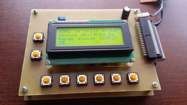
He discovered some 6502 chips (Polish language, Google Translate link) that a Chinese manufacturer was selling, but didn’t really trust that they were legitimate. On a lark he ordered some and upon testing them he found out that they were real 6502s. Building an 8-bit computer is something he’d like to do, but in the meantime he decided to do a project using one of these chips as a general-purpose microcontroller similar to a modern Arduino. The project has similar specs as an Arduino too, including 8kB of RAM memory, 8kB of I/O address space, and various EPROM capabilities. [Marek] went on to build a shield board for it as well, for easy access to some switches and LEDs. It’s a great build that anyone interested in microcontrollers should check out.

Keep in mind that an ATtiny45 has 8 bits like the 6502 but only costs around $1 USD, whereas a 6502 would have cost around $200 in today’s dollars. It’s really only in modern times that we can appreciate the 6502 as a cheap 8-bit microcontroller for that reason alone, but we can also appreciate how it ushered in a computer revolution since competing Intel and Motorola chips cost around six times more before it showed up. They became so popular in fact that people still regularly use them to build retrocomputers of all kinds.

Finite Element Analysis Results In Smart Infill

If you would like to make a 3D print stronger, just add more material. Increase the density of the infill, or add more perimeters. The problem you’ll encounter though is that you don’t need to add more plastic everywhere, only in the weak areas of the part that will be subjected to the most stress. Studying where parts will be the weakest is the domain of finite element analysis, and yes, you can do it in Fusion 360. With the right techniques, you can make a stronger part on your 3D printer, and [Stefan] is here to show you how to do it.

The inspiration for this build comes from [Adrian Bowyer]’s blog, where he talks about adding ‘fibers’ to the interior of 3D printed objects to increase strength. These ‘fibers’ aren’t really fibers at all, but long, thin, cylindrical voids. The theory of this is that the slicer will interpret this as a hole and place perimeters around these voids, effectively increasing the density of the infill in a local area in the print. Combine this with finite element analysis, and you get a part that is stronger where it needs to be, and doesn’t waste plastic.

However, there is an easier way. Fusion 360 and ANSYS Finite Element Simulation are both free-ish tools that allow for some amount of finite element analysis on an imported 3D object. This can be used to find the weakest part of any 3D print, and it can this can be exported as a 3D mesh. Slic3r has a modifier mesh function, and combining this finite element analysis mesh (printed at 100% infill) with the original part (printed at 10% or so infill) results in something that’s strong where it needs to be, doesn’t waste plastic, and is much easier to set up than [Adrian Bowyer]’s ‘fiber’ technique.

After printing a few 3D printed hooks with varying degrees and techniques of infill, [Stefan] found the baseline of 2 perimeters failed in a test hook at about 50kg load. The Smart Infill hook failed at about 100kg. Not bad, and the fancy-pants hook only weighs about 30% more.

You can check out a video of the entire toolchain and testing below. Thanks [Keith] for sending this one in.

Continue reading “Finite Element Analysis Results In Smart Infill”

A 3D Printer To PCB Miller Conversion

Got a 3D printer? With a bit of work, you may also have a PCB miller. That’s the basis of this neat hack by [Gosse Adema], who converted an Anet A8 3D printer into a PCB miller by building a holder for a Dremel rotary tool and adapting the GCode. This approach means that the adaptations to the printer are minimal: the only hardware is a 3D-printed holder for the Dremel that replaces the print head. The result is an impressive PCB milling machine that can do double-sided PCBs and make through holes.

The excellent write-up that [Gosse] did on this hack describes how he converted the printer, and how he took an EagleCAD design and converted it into four GCode files. That’s one for each side of the PCB, one for through holes and one for the final outline of the PCB. These are then fed to the 3D printer and cut in turn with an appropriate milling bit on the Dremel.

We’ve featured a few similar conversions before, such as this vintage conversion of a Makerbot and this cheap engraver conversion, but this one is much more detailed than those, covering the entire process from PCB design to final product.

The TRS80 Model 100 Gets A Brain Transplant

We’ll forgive you if you were busy in the ’80s, and missed the TRS80 Model 100. It was a portable version of the original, ran on four AA batteries, and even had an integrated acoustic coupler which proved handy for workers on the go. However, time is rarely kind, and [Trammell] had come across a non-functional example for just $20. It was time to bring this relic screaming into the modern age.

The motherboard was toast, so [Trammell] decided to wire up a Teensy++ directly to the Hitachi HD44102 display driver chips. Being an older LCD, the display needed a negative bias voltage, so a few diodes, capacitors and a PWM line stepped in to create a charge pump. There was no character generator on board, so the heavy lifting is all handled by the Teensy itself. The keyboard was a simple enough matrix design, so that was wired straight up.

[Trammell]’s work with this iteration got as far as acting as a USB serial terminal, and there was some work done on VT100 emulation. However, according to Twitter, the next stage involves an iCE40 FPGA and some music with which we’re altogether too familiar.

[Trammell] owns a working Model 100, too – employed in some modem experiments, no less.

R/C Whirlygig Is Terrifyingly Unstable

In the days during and immediately after World War II, aerospace research was a forefront consideration for national security. All manner of wild designs were explored as nation states attempted to gain the upper hand in the struggle for survival. The Hiller Hornet was one such craft built during this time – a helicopter which drove the rotor through tip-mounted ramjets. Unsurprisingly, this configuration had plenty of drawbacks which prevented it from ever reaching full production. The team at [FliteTest] had a soft spot for the craft, however, and used it to inspire their latest radio controlled experiment.

Initial experiments consisted of a modified foam wing from a model seaplane, with two left wings facing opposite directions, and joined in the middle. Two motors and props were fitted to the wings to provide rotational motion. After some initial vibration issues were solved, the improvised craft generated barely enough lift to get off the ground. Other problems were faced with centripetal forces tearing the propellers off the wing due to the high rotational speeds involved.

A second attempt started from scratch, with a four wing setup being used, with much higher camber, with the intention to generate more lift with a more aggressive airfoil, allowing rotational speeds to be decreased. The craft was capable of getting off the ground, but instabilities likened to the pendulum rocket fallacy prevented any major gain in altitude.

We’d love to see a redesign to solve some of the issues and allow the craft to sail higher into the air. If you think you know the solution to the whirly bird’s dynamic problems, be sure to let us know in the comments. It should be possible, as we’ve seen successful designs inspired by maple seeds before. Video after the break.

[Thanks to Baldpower for the tip!]

Continue reading “R/C Whirlygig Is Terrifyingly Unstable”

Hacking The Humble Roadster Bicycle

Think of bicycles, and your first mental image could be something pretty fancy. Depending on which side of the sport you favor, you could end up thinking of a road bike or an MTB, maybe DH, CX, BMX, TT, tandem or recumbent.

But for people in most parts of the World such as Asia, Africa and South America, the bicycle conjures up a very different image – that of the humble roadster. And this simple, hardy machine has spawned innumerable hacks to extend its usefulness and functionality by enterprising people with limited means. For them, it is not as much a means of transport, as a means for livelihood and survival.
Continue reading “Hacking The Humble Roadster Bicycle”

Make Your Own Phosphorescent Material

Phosphors are key to a whole swathe of display and lighting technologies. Cathode ray tubes, vacuum fluorsecent displays, and even some white LEDs all use phosphors to produce light. [Hydrogen Time] decided to make a green phosphorescent material, and has shared the process on Youtube, embedded below.

The aim is to produce zinc sulfide crystals doped with copper impurities. This creates a phosphor with a familiar green glow. [Hydrogen Time] starts by noting that it’s important to make sure all chemicals used are of good quality, as even slight impurities can spoil the final product.

Zinc sulfide is made into an aqueous solution, before a highly diluted copper sulfate solution is added, along with ammonium chloride to act as a flux. The mixture is stirred, before being heated in a tube flushed with argon. After firing, the phosphor is washed with water and allowed to cool.

The final product is demonstrated to glow a vibrant green under UV light, showing the process to be successful. [Hydrogen Time] intends to use the homebrew phosphor in future work to produce a display. It recalls us of [Jeri Ellsworth], producing her own EL wire at home. Video after the break.

Continue reading “Make Your Own Phosphorescent Material”