
Today’s story is one of victory and defeat, of mystery and adventure… It’s time to automate the garage door. Connecting the garage door to the internet was a must on my list of smart home features. Our opener has internet connection capabilities built-in. As you might guess, I’m very skeptical of connecting a device to the internet when I have no control over the software running on it.
The garage door is controlled by a button hung on the garage wall. There is only a pair of wires, so a simple relay should be all that is needed to simulate the button press from a Raspberry Pi. I wired a relay module to a GPIO on the Pi mounted in the garage ceiling, and wrote a quick and dirty test program in Python. Sure enough, the little relay was clicking happily– but the garage door wasn’t budging. Time to troubleshoot. Does the push button still work? *raises the garage door* yep. How about the relay now? *click…click* nope.
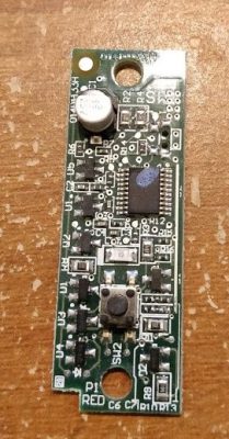
You may have figured out by now, but this garage door opener isn’t just a simple momentary contact push button. Yes, that’s a microcontroller, in a garage door button. This sort of scenario calls for forensic equipment more capable than a simple multimeter, and so I turned to Amazon for a USB oscilloscope that could do some limited signal analysis. A device with Linux support was a must, and Pico Technology fit the bill nicely.
Searching for a Secret We Don’t Actually Need
My 2 channel Picotech oscilloscope, the 2204A, finally arrived, and it was time to see what sort of alien technology was in this garage door opener. There are two leads to the button, a ground and a five volt line. When the button is pressed, the microcontroller sends data back over that line by pulling the 5 V line to ground. If this isn’t an implementation of Dallas 1-wire, it’s a very similar concept.
The wire protocol appears simple enough to reproduce, ideally with an opto-isolator. I found a suitable chip and got it on order. With the physical interface sorted, it was time to move on to the data itself.
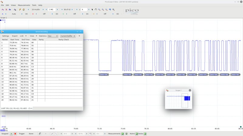
So, what does the request to open look like? “Open Sesame”? The Picoscope software is capable of signal decoding, so some futzing with those settings got reproducible results. UART at 9.6 kbaud. 38 bytes of data were being sent over the wire, and the next step was to capture several of those packets to look for patterns.
Each packet started with a repeatable pattern that Picoscope decoded as 55 01 00. A header of sorts? A source or destination identifier? So far, I just didn’t have enough information to tell. Other than that pattern, the data appeared to be random. So where to from here?
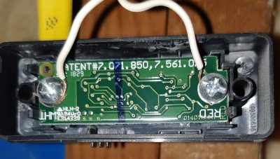
The underside of the switch lists a couple patent numbers. Patent applications often have lots of useful information that is not available anywhere else. Patents also show off legalspeak at its worst. Wading through patents like 7,561,075 does yield the occasional nugget. It describes an encryption (or obfuscation) scheme revolving around a simple transformation. Looking at the patent documentation, I suspected it would be possible to break the encryption scheme and spoof the garage door button being pressed.
A Python script to do the data processing was my next planned move. With a little luck, I thought I could re-create the algorithm, as well as potentially recover the secrets used to generate the data. Many a project have been derailed when the needs of real life have intruded in the life of the hacker, and I’m not immune. For about a month, that’s where the project languished. We’ve moved into the house, my firstborn is a week old, and it’s time to finally get the garage door working.
Spoof the Button, Not the Cryptography
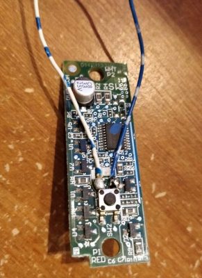
Remember how we started by looking for a simple push button switch? It turns out, there is such a switch built in to the wired opener. Soldering leads onto that small button is the fastest to implement, if not the most elegant. Yes, my solution is a Raspberry Pi running a relay, and that relay bridging the tiny physical button on the wired opener.
Elegant but complicated solutions can be major pitfalls to getting stuff done. Sometimes you have the time to dig in and put together the ideal solution, but sometimes you just have to get the project done. If it’s cheating and it works, it’s not… Ok, it’s still cheating, but it works, which is more important.
We can open the garage door from a command line on the Raspberry Pi. That’s useful, but perhaps a bit clunky. Remember way back in the first article, I mentioned using flask to create a RESTful interface? Here’s where we can really get started.
from flask import Flask
import time
import RPi.GPIO as GPIO
app = Flask(__name__)
GPIO.setmode(GPIO.BCM)
GPIO.setup(20, GPIO.OUT)
GPIO.setup(20, GPIO.LOW)

@app.route("/")
  def hello():
  return "Hello!"

@app.route("/moment/<pin>")
  def moment(pin):
  changePin=int(pin)
  GPIO.output(changePin, GPIO.HIGH)
  time.sleep(.5)
  GPIO.output(changePin, GPIO.LOW)
  return "OK"
if __name__ == "__main__":
  app.run(host='0.0.0.0', port=80, debug=False)
This runs a rudimentary flask server, listening for http connections. Here the relay is on GPIO20, and so the server is waiting for a request for “/moment/20”, at which point, it flips that GPIO high for a half second, triggering the garage door. In order to run automatically, I’ve saved this to /usr/local/bin/gpio-flask.py, and then defined a systemd service at /lib/systemd/system/gpio-flask.service:
[Unit]
Description=Flask Service for GPIO
After=multi-user.target

[Service]
Type=simple
ExecStart=/usr/bin/python /usr/local/bin/gpio-flask.py
Restart=always

[Install]
WantedBy=multi-user.target
Telling systemctl to enable and start that service gets us in business. One last piece of the puzzle, let’s build a control page on our PXE server.
<!DOCTYPE html>
<html>
<body>
<div style="text-align:center">
<form method="post">
<input type="submit" name="GDO" value="Cycle Garage" style="padding:25px 15px;">
</form>

<?php
  if ($_SERVER['REQUEST_METHOD'] === 'POST') {
    if ($_POST["GDO"]) {
      $curl_handle = curl_init();
      curl_setopt( $curl_handle, CURLOPT_URL, 'http://garage/moment/20' );
      curl_exec( $curl_handle );
      // Execute the request
      curl_close( $curl_handle );
    }
  }
?>
</body>
</html>
We’ll expand on this PHP script more in the future, but for now it has two functions. The first builds and displays the interface page — just a single big button labelled “cycle garage”. The second part of the script only acts when a POST request is received. If the “GDO” value is present in the request, it uses curl to fire off the command to our Raspberry Pi, raising the garage door. It’s been a long road, but it finally works. A button on a web page opens my garage door. Let me relish my small victory for a moment…
Now that we’ve cheated our way past the garage door opener, next time we can work on data logging and HVAC control. Until then, happy hacking!


Kinda disappointed the crypto part wasn’t pursued, would be interesting to see it get dismantled (working on a similar thing this exact moment). Also, the WordPress code block formatter seems to have butchered the Python code blocks.
Some of the formatting did indeed get eaten. Should be fixed now.
I wanted to dig further into the crypto, but that’s how it goes sometimes. If I ever get back to that particular rabbit hole, I’ll be sure to give an update.
Wives tend to get mad when you spend long hours in IDA or trying to dump chip firmware.. I don’t think frequency analysis or brute force would of worked here it probably used some rounds of xor and byte-shift off a seed at the least to transform bytes..
Raspberry pi is Overkill. (Unless it is running node-red).
Arduino is better sized, and can be controlled using a phone:
http://enginemonitor.blogspot.com/2015/08/garage-project-update.html
If that were the only thing ever to be connected in the garage, then yes, definitely overkill. One of the points of the whole project is to have a flexible platform, the Pis, in every room. So far I also have a temperature sensor in the garage, with plans for more. Stick around, there’s more to come. =)
Pi is still overkill and less robust because of the SD card. No need for a full computer here. A micro controller with wifi (e.g. ESP8266) is more than enough to control multiple relays and handle data from multiple sensors.
Go read the rest of the series. No SD card, these Pis are booting entirely over PXE. Yes, there are other ways to do it, but this seemed the most interesting to me.
Connect a camera, open-cv the number plate(s) and tell the garage door to open!
Only works in states that have FRONT and REAR plates, many do not — Unless you always want to back into your garage.
No, I nearly never drive backwards into the garage. But as cheap as cameras are these days, it would be easy to use a second camera on a post.
And of course *no one* could ever spoof numbers and letters on a rectangle… ;p
I haven’t written the rest up. I only have one pi, and a bunch of 8266s. Using node-red everything can talk to everything.
That is also the approach I use. I lot of ESPs (8266 or 32 depending on the needs) using MQTT to communicate with a Pi based hub running Node-Red. The Pi notifies using text and email services and provides a second, separate, secure MQTT interface with client side certificates for Android Apps to use. Other Pis do voice control using Snips and other local services. “Cloud-free IOT”!
A phone paired with bluetooth.
Verses a Pi on an IP.
hmmm
$5 raspberry pi zero w isn’t overkill plus you can add a temperature sensor for home assistant along with cheap reed switches to see if the garage is open or closed or use it to log how the garage was opened by button or remote or display the status on home assistant. You can also have it have it’s on GUI by itself and creating a shortcut to the URL on your phone. Then you can expand on it using the rest of the relays like controlling lights or yard sprinkler system etc. Plus there is a huge community that has pre built software for the raspberry pi zero w for this exact job. SD cards are cheap you can get a 16GB for like $3 on amazon and if you don’t already have camera’s in the garage you could buy a cheap pi camera and have a live feed. I could see if it was just turning on a light it would be over kill but putting a pi in the garage allows you to have one in there for future projects. Mines hidden the garage unit itself and the reed switches are attached on the part where the chain rides so you pretty much can’t even see it.
Nice work. I did something similar very recently with an OrangePi PC and a stripped remote. My opener has no connectivity of it’s own and I added a couple of webcams using motion(the software) to create streams. I have not gotten as far as making any kind of UI for it so I control the door as need at the CLI.
Mine was kind of bodged together in a hurry. We suddenly had to start letting my son be home alone sooner than originally planned. I wanted to make sure he closed the damn door after letting himself in with the keypad. Then I thought “oh crap, what if he has problems?”
If you haven’t seen it already the leosac project might be of interest to you. http://www.leosac.com
I am wondering why the original button is so complex. It doesn’t seem to improve security or add functionality so why the extra expense? My opener just has a simple button and I use an ESP8266 to control it. It uses WPA2 security with a 64 character truly random key to communicate with a dedicated IOT access point connected to a Pi hub. That provides more than enough security for a garage door.
So that a burglar can’t just short the wires to open the garage door. Makes perfect sense.
Isn’t being in the garage with the garage opener a form of “root”?
SUDO push button
X)
Consider a case where a burglar tries to access button wires from outside. You see wires can be accessed from very narrow slits, buttons can not. Wire shorting may be easier then a button press. I think it is a nice idea (though came up as roadblock here.) Another reason could be, if button goes bad, you can buy it at a very ‘premium’ price only from original manufacturer and can not simple replace it with a commodity switch.
Chain saw.
My guess would be that the button is essentially producing the same signal as the remote so that it all goes into the same system. This would also allow for the outside keypad, so the manufacture just opted to have one access route and not provide the “root” access of a hardwired switch.
I suspect they did it to upsell customers into their own IoT add-on.
So you have to buy the genuine button from them, and they can charge whatever they want.
Which is why I keep fixing our 20 year old openers. Just a button.
because the wall unit does more than just signal ‘open/close’. It also tells the opener what wifi credentials to use or to turn the lights on/off.
That would make sense for an outdoor mounted PIN pad. Perhaps they just wanted to use the same interface. The garage door opener from my parents has both possibilities: terminals for wired local pushbuttons (just close the contact) and an outside mounted number keypad which communicates encrypted to a “receiver” over a 2 wire bus. That then again has an output relay.
Next would be to have a sensor to tell if the door is open and an open and close button. You dont want to get a contact bounce causing the door to be left open :(
Shouldn’t it already have one as a part of safety?
The door sensors for safety don’t tell you if the door is open or closed. They just sense if something is in the path of the door, and stop/reverse the motion of a closing door if something breaks the sensor beam. Most door open/close sensors I have seen use tilt sensors mounted on the door that detect if the door is closed (vertical) vs open (horizontal). Smarter sensors can even detect vertical-to-horizontal and horizontal-to-vertical transitions as opening/closing events.
Or just get one of these: https://www.geniecompany.com/aladdinconnect/default.aspx which not only opens and closes the door remotely, but tells you if it is open or closed. Sorry to be such a party pooper.
Those are great, if you’re willing to trust the vendor and their closed source firmware. :P
How about this then: http://garagedoorbuddy.com/
The modules (door opener, door sensor) are basically just little boxes with ESP8266MOD modules in them plus a bit of discrete logic (relays for door open/closer, hall sensors for door open/close sense). Toss their programming and come up with your own ESP8266 code. So the hardware is ‘closed’ (sort of, they won’t give you schematics) but you can roll your own firmware, should you so desire.
Yeah… spend money buy anything. Why on hackaday then ? And where is the fun in buying ?
Or get one of these https://opengarage.io/. Open source, restful API, website, wifi enabled, easy to install, and generally just works. Not only can it tell if your garage door is open or closed, but also if there’s a car there. You could even tell which car if they are lucky enough to be significantly different in height, like say a sedan and a SUV. I have one and am quite pleased with it.
Its called a “rolling code” , and a Pi to do what a $5.00 ESP32 could have easily just have done. Talk about overkill.
I think I would’ve gone for that internal-pushbutton-bridging approach too… (on the motor housing itself if there is a “test” button there). Simple to do and relatively fool proof, with minimal intrusion into the circuitry and little fiddly wiring to do. Who cares what internal data protocol is used, one day the motor will break and your hack will be more likely to be adaptable to another model if you just emulate simple button pushes, rather than trying to “speak” with the thing in its own quirky language.
I recently did something similar using WiFi Wireless Smart Switch Relay Module.It works with IFTT/Alexa/Google Home too. Got separate smartphone app called ewelink. costs $10 only and similar wiring to trigger the button.
Every one of those boards has test points for a “momentary switch”. All you need to do, is find them, and hook up a relay.
— guy who has installed about 30 of these over the years
The initial byte (0x55) is a common message start byte for RS232-like systems with auto-baud rate detection because it alternates set and clear bits allowing the receiver to acquire the bit clock accurately even if it differs wildly from the expected baud rate.
Some microcontrollers’ embedded UARTs have an auto-baud mode where they will automatically tweak their baud generator divisor whenever they see the right number of evenly spaced transitions after some set idle duration. Some limit this functionality to small tweaks (or small tweaks per 0x55 byte) while others can lock to any supported rate given their base clock with a single 0x55 leading byte.
So long as the protocol spoken both contains predictable inter-message idle times and tolerates ignoring or harmlessly consuming 0x55 bytes at the start of a message this can provide a great deal of flexibility and resilience against baud rate mismatch due to relative frequency drift between the sender and recipient’s clocks. This is especially useful when the sender is a low cost micro using a built in RC oscillator as a clock source.
Basically how I ended up resolving the door at work, we *really* need a remote with a high powered transmitter (or an amplifier on the existing remote) cos it has a bit of concrete to go through and it works dependant on weather conditions.
It’s just an usb power brick, 3.3v regulator, ESP8266 + 4066 + existing garage remote – jobs rather unattractively done.
Er, why not just use a nodemcu? https://github.com/konnected-io/konnected-security ties into smartthings directly and has a pushbutton interface. (That is how our slightly-too-smart coffee pot is activated these days..)
I’ve done similar with an Arduino an HC05 Bluetooth module. Using Bluetooth allowed me to access the opener via smart phone without going through a WiFi connection. I really didn’t need internet access, and felt that it was safer from outside hacks. My door opener was older and only needed a half second pulse to get the job done. I also added buttons to turn lights. on and off. To create an app for the phone I used MIT’s App Inventor. Mine works but is a bit crude in some ways, as I’m not all that proficient at Bluetooth. I hope to get back to it to provide
Norro211 mentioned:
So that a burglar can’t just short the wires to open the garage door. Makes perfect sense
Doesn’t that depend WHERE the two wires are? If they short the two wires that are the button wires…….
I see a fundamental flaw with the idea in that once you “expose” the wires to the switch outside the unit, shorting them together will be the same as pushing the button.
Just on another topic, looking at the picture where you attache the wires to the existing switch:
Where did you get the wires? (What technology)
It’s telephone jumper cable. Essentially the same thing as a single pair out if an Ethernet cable.
I thought I recognised the colour code.
Did the same thing with my heating. Just linked up the remote 433 sender and powered it up when needed. SImple
Interesting. I kinda went down the same path with the remote control for my adjustable bed. At first, i thought about just wiring into the remote, and using relays to trigger the buttons. I decided I wanted to keep the remote functional, so I went down the path of replicating the remote. Using FCC ID’s and pulling the remote apart, I found it used a CC2500 controller, which had some arduino libraries. Using an arduino and a CC2500, i was able to receive the signals sent and repeat them (it was a bit more complicated than that)
I ended up using a Particle Photon that I had, and can now control the bed from SMartThings or Alexa :)
“Alexa, turn on the bed!”
Just a note, the Flask code posted appears to be using HTTP GET. I don’t believe that’s a good idea, as GET requests are supposed to be idempotent — that is to say, it’s not supposed to change anything. A proxy might cache and re-run the request, triggering the garage door to flip, as happened in this twitter thread: https://twitter.com/rombulow/status/990684453734203392?lang=en
Using POST would be a better decision!
The user-facing stuff is using POST, for exactly these reasons. Point well made, I’ll look into Flask and POST for the future.
Good work, and a sensible solution. I’ve resorted to similar hacks. It feels wrong as a hacker, but it works perfectly reliably.
But it amazes me the complexity and security issues you have with garage doors in the US – in the U.K. they just have a physical lock on them (a simple eurolock), and thefts from garages are extremely rare provided the garage is attached to or next to the house.
Some places garages in blocks separate from the houses, usually where the houses were built in some “carless city of the future” left-wing wet dream, and a separate block of garages was added after. Those do get thefts, but it’s fairly easily recitified with a secondary lock on the door.
And how do you remote control these locks? Especially when it’s cold or raining (AFAIK most of the time in U.K.) it is very convemient and time saving to have a remote controlled garage door opener.
Amazing. I tried several projects and all came to a halt at the point of connecting the relay to the garage door opener. The assumption of other projects is that you just wire the relay in parallel with the door-bell style wall button. The elegance of your solution is the genius of simplicity.
In a Jeff Spicolli moment, I said, “I know that circuit board!” It’s the one inside my (now dead) wall button. Then I realized how little I know. Like which two of the four connections to the board’s tiny little button do I solder my wires from the relay to? Is there a question of the voltage from the relay to the mini-button?
I would appreciate a Hand up, if possible.
https://images.app.goo.gl/1tY4MNi9rzXQ5Y1U8 those are wired internally like this. I would take a scrap of wire, and jumper across the switch, trying combinations till it works. Or take a multimeter, and figure out which leads are permanently tied together.
Thank you! Will try.
Seemed like this project started off as one thing and then changed to another. I have a 888lm controller… it can ‘press the button’ to open / close the garage door using 2 wires to the garage door opener… BUT using those SAME TWO WIRES,.. it can figure out of the door is open or closed….. I’d like to figure out how that part works. It must be part of the protocol that is sent over the two wires… from the garage door opener to the 888lm device. I’d like to get rid of my 888lm and liftmaster internet gateway and use a pi. I can do this for the simple complete the wire connection and open / close the door…. but I’d like to be able to decode the protocol sent over the wires to get the garage door status ( open / closed ) and not use a external device like a mechanical switch to figure out if the door is up or down. Has anyone figured out the protocol that these garage door openers use?