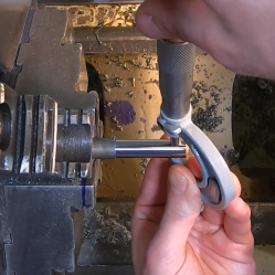
When designing parts on a screen, it’s very easy to type in a bunch of nice round numbers and watch everything slot together in perfect harmony. Unfortunately, the real world is not so kind. A 10mm shaft will not readily fit in a 10mm hole, and producing parts to perfect dimensions simply isn’t possible. This is where fits and tolerances come in, and [tarkka] have created a practical demonstration of this on Youtube.
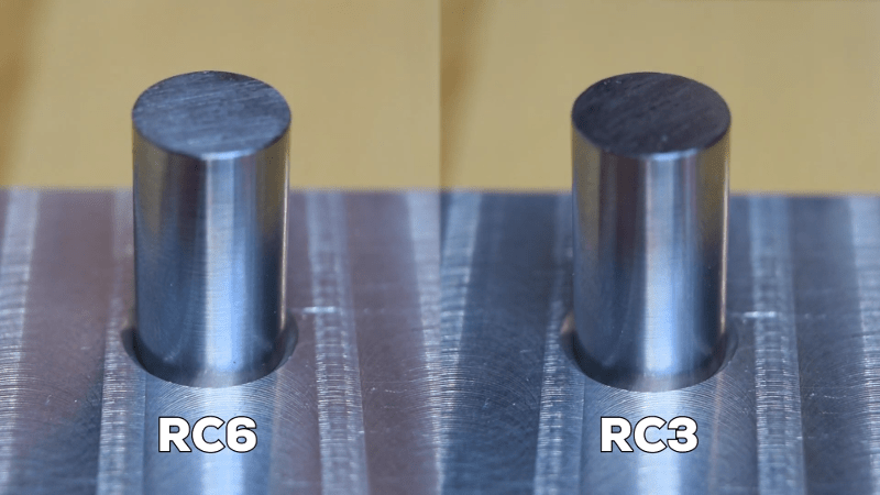
Hole and shaft tolerances are important to ensure parts mate correctly and as intended. If a shaft is to fit into a hole easily and the dimensions aren’t critical, a clearance fit is called for. If assembly should be easy but the part is required to locate accurately, a running fit is called for. Alternatively, if the parts are intended to be pressed together permanently, an interference or force fit should be used.
The video covers the basics of fits and tolerances in an easy to understand way, with visual examples. The fits discussed are based in Imperial measurements, but the metric standard of hole and shaft tolerances (ISO 286-2) is also noted.
Getting your tolerances right is key to making good parts – we’ve covered common issues such as tolerance stacking before. Video after the break.


One mistake that some make is over-specifying tolerances, i.e. each part must be to 0.001 (measurement unit of choice) when 0.05 would more than suffice. I have seen a project use as a template a high-precision part that had critical fit for a box that was going to sit on a test bench. As one of the photo captions above states, higher precision means higher costs, and in this case only because a purchasing agent questioned the cost did a $250 enclosure not end up costing us $3500.
OMG… I fought this battle SO many times during my 25 years as an engineer. Precision costs MONEY. Most times a three decimal hole diameter costs more than a two decimal hole. Many times the tighter tolerance hole can be used for location and the second hole can be a slot, allowing the location of the two holes to also hold a lesser tolerance. It all adds up.
One important point that takes a while to sink in is that this information is automatically encapsulated in your drawings. If you’re not careful, the CAD system you’re using will merrily call out numbers like .3125″ in the dimensions when you plugged in was “=5/16″ because you really just care about having a hole for a 5/16″ bolt.
The thing is that when a machinist or bidder looks at your drawing he doesn’t know that, and since you *spec’d* it to 4 decimal places, he’s going to *bid* it at 4 places, and charge you for a +/- .0005 drilled and reamed hole.
One place this always seems to bite is when people place a metric pattern on an imperial part, and instead of a 100mm hole pattern (precision .2mm/.008″ implied) the CAD system dimensions it as an imperial 3.937″ (+/- .003” implied)
That’s already a problem with the way the American units are used with non decimal fractional parts, not only with unit conversion. But it be could easily avoided by explicitly specifying the required tolerances.
Exactly, all dimensions must include +/- tolerances. If I send a drawing to tooling without tolerances, they immediately bounce it back.
On Solid Works at least, on the print you can pull hole details out using its own tool.
On other dimensions, you can set the precision in the global settings, and edit individual dimensions as needed. But then, I still like to play with our tool makers a little game I call “guess the missing dimension”
Elliot’s rules of thumb for 3D printing: tune for your own printers, naturally. (Machinists look away!)
0.1 mm = tight/force fit
0.2 mm = removable tight fit (not sure if this is “transition” or “running” — depends on the phase of the moon)
0.3 mm = loose fit
But that video is rad!
Yeah, those sound about right for detailed prints.
With my UP! printers at 0.35mm slices with a 0.4mm nozzle they are around 1.75x to 2x of above values.
Those look familiar. I add 0.15mm to the radius of a hole and subtract it from the radius of a shaft, though the 0.15mm is in a named variable. This is for printing at 0.14mm layer height, but for milling wood and acrylic too.
Mk3s? I independently arrived at the same fit conclusion.
I work in a tool and die shop- and we still yell at engineers who over tolerance stuff.
One engineer always lists every dimension to 0.0001″, and I constantly have to ask him what dimensions actually need to be +/-0.0001″. I want to smack him often.
The difference in time for even a simple fixture can be several days if it all has to actually be 0.0001″ fits, learn to dimension tolerance properly if you want to have your parts made by a shop- it will save you thousands, no joke
Company I worked at had a spacer for an alternator that cost $25 to have made in quantity. Turned out it was speced to .001 – and a piece of black water pipe would have worked fine.