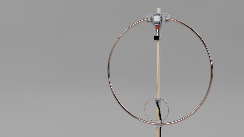
Antennas come in many shapes and sizes, with a variety of characteristics making them more or less suitable for various applications. The average hacker with only a middling exposure to RF may be familiar with trace antennas, yagis and dipoles, but there’s a whole load more out there. [Eric Sorensen] is going down the path less travelled, undertaking the build of a self-tuning magnetic loop antenna.
[Eric]’s build is designed to operate at 100W on the 20 meter band, and this influences the specifications of the antenna. Particularly critical in the magnetic loop design is the voltage across the tuning capacitor; in this design, it comes out at approximately 4 kilovolts. This necessitates the careful choice of parts that can handle these voltages. In this case, a vacuum variable capacitor is used, rated to a peak current of 57 amps and a peak voltage of 5 kilovolts.
The magnetic loop design leads to antenna which is tuned to a very narrow frequency range, giving good selectivity. However, it also requires retuning quite often in order to stay on-band. [Eric] is implementing a self-tuning system to solve this, with a controller using a motor to actuate the tuning capacitor to maintain the antenna at its proper operating point.
If you’re unfamiliar with magnetic loop builds, [Eric]’s project serves as a great introduction to both the electrical and mechanical considerations inherent in such a design. We’ve seen even more obscure designs though – like these antennas applied with advanced spray techniques.


Once upon a time I needed a transmitter/antenna to measure the attenuation through rock (300 feet of quartzite) at VLF (25 KHz), long story. I found a 30 foot piece of 50 pair telephone cable, and spliced the ends together to get a 100 turn coil. For a transmitter I used a 5 volt 200 amp power supply and wound another secondary on the power transformer and fed the antenna with that. It worked OK.
I did similar but with DC for a DIY seat heater in my jeep. I had a roll of stranded Ethernet cable that someone had bought by mistake that had been sitting around forever. I took a long piece of it and turned it into a big flat loop and trimmed it back until it got just warm enough to feel nice on a cold winter morning. I had pondered making it shorter and using electronics to get it warm fast and than back off, but in the end simplicity won out. Also the way I did it a shorted FET could not catch my seat on fire.
Nice design at a hefty price for the vacuum variable capacitor alone. The cheapest I found starts at approx. 200 US$ on ebay… https://www.ebay.com/itm/Comet-CVBA-500BC-5-BEA-L-Vacuum-Capacitor-/183627655792
This is Eric. I think I got the vacuum variable cap for $120 so it’s possible to get it cheaper if you wait awhile. There are also some Russian vacuum variable caps that I’ve seen others use with success.
Eric, I’m concerned about your plan to use the hard stops of the vacuum cap to home your motor on startup. As I recall, these capacitors use a metal bellows attached to the shaft to maintain a hard vacuum and allow movement. I wonder if there’s a lifetime associated with cycling to the end stops.
Also, some of these capacitors can withstand hitting one hard stop better than the other one (min or max).
An alternative to using either extreme of movement would be to use a mid-point sensor that switches from on to off in the middle of the range or, even better, near the typical working position. At startup if the sensor is off, move until on. If on, move until off and then restart the home routine. You’ll probably only use a portion of the full range anyway and if the sensor is near the target, it’ll hardly move to get home.
Hi RP, thanks for the info. I’ve been a little concerned about this, too. I’ve been experimenting and since the motor movement is very smooth I can drive it with low current and detect the “stop” with very little overtorque required.
On my particular varicap if I try to turn the adjustment knob clockwise it bottoms out and feels quite solid. At the extreme range In the other direction part of the varicap starts to unscrew and I won’t unscrew any further in case it causes damage or breaks the seal.
Can you explain any more about using a midpoint sensor? The issue I am trying to solve is that the capacitor has a working adjustment range of over ten full turns. When I first turn on the loop antenna I won’t know if I am on turn 1,3,8, etc. In order to home properly I’d need to design a mechanical feature to track turn count or become very diligent about tracking turn counts and storing them to flash. If it was only one turn, I could easily use something like a microswitch and a plastic flag.
For now, the low torque required to home the position feels acceptable to me, but I will continue to monitor the varicap for damage or changes in performance. I will also investigate to see if there is a maximum torque spec for adjusting against the stops. If I find anything, I’ll put it up in a subsequent article.
Since you have a 3D printer, consider printing a worm gear to go in-line between the motor and varicap with a meshing spur gear at the side. Perhaps it could replace the shaft coupling you have now. I think you could easily get a 10/1 ratio this way.
The brackets to hold everything can also be printed and since it’s both slow and a low torque gear set, it should last a long time. You could print a cam lobe on the side of the spur gear to trip a microswitch or optical beam-break sensor.
Exactly. One of these would suit my location to a tee if I can find a decent vacuum variable capacitor for a decent price.
In Australia, they’re starting off at about $300
73’s all.
Magnetic Loop antennas are amazing performers, especially for their physical size. The capacitors are tricky for tuning and require high voltage types so as not to arc. They have been used for years on ships for both their size and narrowness of frequency. The narrowness of their frequency makes them less succeptable to both in-band interference and harmonic transmission. These antennas have amazing performance that compares to the performance of full size antennas half-wave or higher in the air. They simply cannot be beat in performance for there size for both transmission and reception. They are extremely quiet on receive. The first one I built to start with I thought I had done something wrong or it just didn’t work at all or the band was totally dead, until a station in Nova Scotia came blasting in at 45dB over S9. The second surprise was when that station gave me a similar report. We were both using 100 Watts or less on transmit. After playing around with that antenna for just one day I was sold. These antennas are simply amazing. They are relatively simple to build. They are very forgiving in construction. Almost nothing is difficult or very specific about their build except for the resonating capacitor’s charactoristic’s. The rest is very flexible, I have used many materials for the actual construction of the loop, the feed, and the support assembly. I have also used many different feed methods, I like a secondary small loop the best for it’s simplicity, and effeciancy. As far a the capacitor is concerned the vacuum variable reigns supreme, however other high voltage caps work well too. WB4IVG Laurin
This is Eric (AA7AJ) from the article. Thanks so much for the story and info! I’ve been so busy working on the antenna I’ve barely used it. I’m looking forward to trying it out!
Do you think you could help build me a device that utilizes loop antennas? Help
Sure I can contact me my info is on QRZ.
Laurin WB4IVG
a schematic would help be understand…. if it is done well… or a pictorial….
Agreed! I will eventually lay out a board for this and at that time will be able to publish a schematic and board file. Check back in a few weeks and you’ll probably find it.
W8JI has much info about them on qrz and eham if you search the forums. I ended up buying a mfj loop tuner and used flexible copper tubing. I think it uses a purpose built butterfly capacitor. Cool antennas and fun to play with.
That being said a low dipole tossed up however or even a random wire out a window with a counterpoise seemed to work better for me on wspr.
There is a good video at https://m.youtube.com/watch?v=R71qeIq5WKs&t=1s which shows the build of a small loop constructed of materials from a big box store for $60 plus a vacuum capacitor he found for $50. He uses a HackRF SDR. This is a hot topic for radio hams just now, and there is a gob of literature on line.
George W9ZSJ
Just dinished my magnetic loop. Made it from flat aluminium bar for 28mhz, also made butterfly capacitor from sheet aluminium. frequenty adjustment is done bij 12v dc motor and a pwm works fine. Loop range is from from 10m till 17m. Have spend more time getting my Icom706 ready for wspr and ft8 then in construction of the loop
For vac tube go to old tv guy close to you, you may find one below $50.
Eric, I recently came across your interesting work on the magnetic loop antenna using a Comet CVBA-500 vacuum variable.
I am in the planning process for a magnetic loop antenna, and also have a Comet CVBA-500 capacitor. On checking the data sheet (downloadable from the Comet web site), I notice that the maximum current handling of 57A rms is valid only near 14MHz when the capacitor is set to its 500pF maximum value. The maximum current rating is considerably reduced as the capacitance is reduced.
Using the mag loop modeling program written by G4FGQ (RJELOOP1), a 3 ft diameter circular loop operating on 14MHz requires a resonating capacitor of about 50pF. According to the Comet data sheet, at 14MHz with the capacitor set to 50pF the maximum current permitted is about 4A rms. With 100W to the loop, the current through the capacitor is about 29A rms. This greatly exceeds the rating of the capacitor.
Have you transmitted with your mag loop yet? It would be interesting to see how hot the capacitor gets.
Jack K1VT
Nice research, I agree the capacitor could get quite hot or fail prematurely.
Brian KEØNJG
100 watts into a mag-loop is greatly unnecessary and should be completely thought out on all aspects of the build. There are multiple frequencies and resistances for said frequencies. But high wattage applications create dangerous voltages with increased risk.