The king of machine tools is the lathe, and if the king has a heart, it’s probably the leadscrew. That’s the bit that allows threading operations, arguably the most important job a lathe can tackle. It’s a simple concept, really – the leadscrew is mechanically linked through gears to the spindle so that the cutting tool moves along the long axis of the workpiece as it rotates, allowing it to cut threads of the desired pitch.
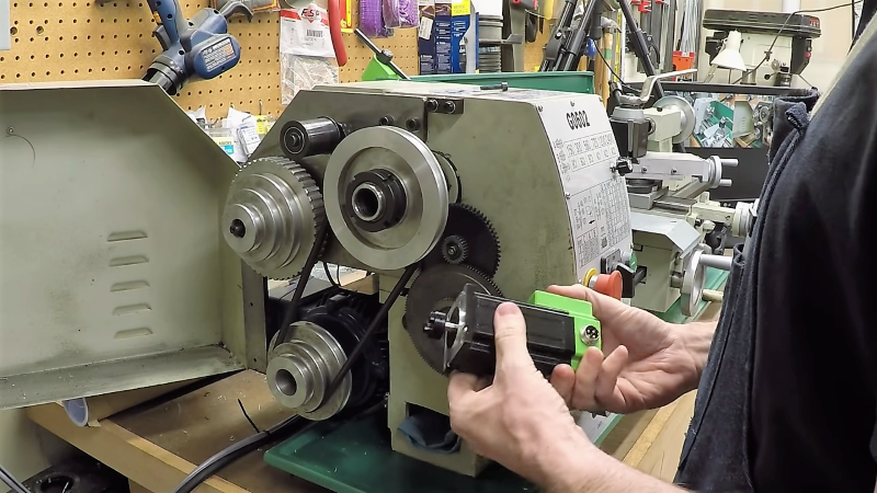
But what’s simple in concept can be complicated in reality. As [Clough42] points out, most lathes couple the lead screw to the spindle drive through a complex series of gears that need to be swapped in and out to accommodate different thread pitches, and makes going from imperial to metric a whole ball of wax by itself. So he set about building an electronic leadscrew for his lathe. The idea is to forgo the gear train and drive the leadscrew directly with a high-quality stepper motor. That sounds easy enough, but bear in mind that the translation of the tool needs to be perfectly synchronized with the rotation of the spindle to make threading possible. That will be accomplished with an industrial-grade quadrature encoder coupled to the spindle, which will tell software running on a TI LaunchPad how fast to turn the stepper – and in which direction, to control thread handedness. The video below has some great detail on real-time operating systems on microcontrollers as well as tests on all the hardware to be used.
This is only a proof of concept at this point, but we’re looking forward to the rest of this series. In the meantime, [Quinn Dunki]’s excellent series on choosing a lathe should keep you going.


I think it’s risky running the stepper in open loop control. Adding an encoder and implementing feedback would make it far more reliable.
Also consider using clearpath servo motors instead of steppers, they have all of the feedback built in and can achieve some amasing repeatability. https://www.teknic.com/products/clearpath-brushless-dc-servo-motors/
Drop-in stepper replacement models: https://www.teknic.com/products/clearpath-brushless-dc-servo-motors/clearpath-sd-stepper-replacement/
“PRICES START AT ONLY $257”
Although it’s impressive that a NEMA23 drop-in replacement can do 858 oz-inches (6Nm) and cost $360, that’s still a bit too much for your average hacker…
Not to sound like a jackass but if you are contemplating making custom screws on a mechanical lathe, number one you had to have enough money to buy an accurate lathe in the first place as well as a thread cutting tool, and more importantly number two- do you have any idea how expensive a full set of gears for most lathes actually costs to run a gearbox for real screw cutting? You’re looking at hundreds of dollars minimum just for the gears.
To be a bit blunt about it while I appreciate thriftiness in making and encourage it I don’t think you realize how much certain things simply cost to do functionally speaking. Only 360$ for the ability to add accurate mechanical screw cutting ability if this works properly it is actually pretty damn affordable.
For the record many people have done this in the last few years. I would definitely encourage closed loop encoder system for this because even a slight misalignment causes a completely useless screw thread.
Better lat(h)e than never, right?
There are so many things wrong with the above reply, it amounts to FUD. Keeping things simple:
Primo: open loop stepper(s) are fine if designed (i.e. not guessed about) and typically provide similar accuracy as a mechanical geartrain.
Secundo: “closed loop stepper-only”??? Bwahaha! If a closed loop system is envisaged, linear transucers are needed (glass scales). Otherwise, it’s no better than open loop.
Tertio: this is not about turning (pun intended) a cheapo chinese “lathe” into a high-performance cnc. It’s about good enough and learning stuff. Which means buying black boxes and stringing them together may not, in fact, be the best approach.
Off my soap box now :)
amazing all these 3d printers can run for days on end without feedback….
Not even close to the same thing.
Actually, having a part start to peel and hitting the extruder on a 3D is a common cause of failures. If you try printing 8 parts and one of them hits the extruder and it misses a few steps the rest of the parts are ruined. It is not unheard of to leave the printer going and come back to see one part knocked off and a bunch of other pieces with a big “skip” in them.
I don’t disagree that closed loop would be better in almost all cases. The open loop system such as this can lead to missed steps and inaccuracy. Getting some feedback (more than an end stop swtich) could result in faster motion without loss of position. You might even get an alert from the machine when position is not where it is supposed to be. Some of the tmc2130 look to give some feedback by monitoring stepper amp usage but an encoder of some type would be nice.
I hand cut threads from scratch for custom tooling at work on a manual lathe earlier this week in a special size. Both external and internal thread cutting.
Do you know what happens without the mechanical feedback of having the lead screw positively engaged the entire time with the headstock?
Do you know what happens if I take a cut even slightly too much and it work hardens the material, moving the cutter under sprung cutting force?
Do you know what happens if I even pump the handwheel out of place before it catches the screw thread and I turn it back to where it was?
The result of all these things is the same- if my direct mechanical feedback system of dials and forces and tool angles changes even in the slightest, I get a completely useless thread that cannot be saved.
A metal screw is not an item you can just do the sandblasting equivalent on to make pretty like acetone smoothing on a poorly made print- it requires consistent and inherent accuracy of a system of mechanical feedback during its creation to properly function.
There is no reason this can’t be done with a digital feedback system like this but only if the understanding of the mechanical accuracy needed in the final object is respected and held appropriately, otherwise it will never function in anything.
A closed loop feedback system would become more and more critical the finer the picture of the thread and the more threads per inch or millimeter the thread becomes.
If you prefer Open Source for closed loop steppers you can have a look at “ananasstepper” or “mechaduino” (There are more similar projects).
You can buy built up PCB’s for these for around EUR45, or spin your own boards and get source from github.
Thank you Paul, had forgotten about these excellent projects.
I’ve designed and built a bunch of machines here at work that use those motors and they’re awesome. The different modes and settings and whatnot you can control them with is crazy.
Ah, replacement for a car’s mechanical speedometer cable (some of us still drive cars that have speedo cables)
Yes, although they are gone even longer than the accelerator pedal cables.
This guy confuses these two statements:
“This will not do real time control”
“I am not able to make this do real time control”
I suspect he is a council worker “sorry about that, the computer did it”.
Depends what he is trying to do… you are correct that this process can be done with the atmega as it is plenty fast enough for a low-resolution rpm sensor. Most threading on LinuxCNC is just orchestrating the spindle rpm (in pps), 0′ deg alignment triggers, and keeping consistent velocity of each cutting pass (the RT part). The HAL supports this already, but the documentation certainly could use some improvement. The RT kernel can be confusing to anyone who hasn’t studied it previously, and understanding how to setup the tool pass can be tricky.
Simple axis velocity control is usually an OK trade-off for a lathe, as the chuck has enough inertia that treating it like a multi-axis robot positioning servo is unnecessary.
We should try to support those who may discover something neat. I know how challenging it is to get arbitrary threading right. I’d give him a 10/10 just for trying the project with a quadrature encoder… kind of like setting your car’s odometer display in mm/s. ;)
Agreed, this is a cool project worthy of review.
I see no reason a digitally controled lead screw can’t be made to function properly with a mechanical spindle. Digitally controlled lead screws are what cnc threading is done with (well, ballscrews, but same concept).
I wonder if it would be possible to thread at high speed or do multiple lead threads using this method when it is not fully CNC.
Multi-point Threading Inserts can get finicky, but they do exist for larger machines.
Check out NativeCAM with linuxCNC, as the OSS lathe CAM macro GUIs are fairly straight forwards.
We pre-install his plugins on the club image (link in username)…. as I really liked the hybrid CNC and classic manual workflow.
;)
You don’t need a quadrature I have threaded for years on a couple of lathes with a 1 pulse per spindle rev “encoder”
Good thinking! Once it’s spinning fast yes it’s probably a negligent benefit of high resolution.
I’m not surprised it will work, though with the imprecision in spindle location i’d expect the threads to be a bit loose and sloppy. Each pass could start almost one full spindle rotation out. (though if you have a gear or two in the mix then that concern goes away, and the backslash in the gears is all that remains – a problem you have to be aware of and work around on a dumb geared spindle too)
True, but (without yet having watched the video to know where HE is going with this) there are advantages. For example, milling or slotting a helical groove is practical with this setup, but not a one pulse/rev. Or, more generally, any case where the spindle speed may not be real stable due to insufficient power, low rotating mass, or unbalanced work. The variation can be pretty significant. (having threaded special size threads for the holding bolt on a single throw crank, I know it can be VERY significant, even on a larger lathe)
I setup my 9×20 lathe with LinuxCNC using a quadrature and index pulses. Quad gives you direction (not important for threading) and four pulses per tooth (important for low speed). I think I ended up with 65 teeth on my encoder disk and have no problems threading or eccentric turning even with very low VFD (30 RPM) speeds or even hand cranking. It’s really nice to turn by hand and see the operation in slow speed to check your setup.
Instead of reinventing the wheel/electronic leadscrew, I think you’d be a lot further ahead using a LinuxCNC or MachineKit on a BeagleBone.
Couldn’t a ESP32 keep up with the encoder?
I did a very similar thing years ago on my fathers lathe. I used a bunch of industrial surplus gear. “Smart” stepper with built in driver, touch screen, atmel dev board, and a motor control board with electronic gearing features. Never did a write up on it though I’m afraid.
It has been working perfectly since it was installed and it makes the lathe an even more useful tool. Cutting can be very smooth when the tool feed can be tuned. And I would never have been able to find gear sets to cut those wierd brittish threads on my vintage bike without this mod. Doing this is highly recommended.
Open loop honestly shouldn’t be a problem for a leadscrew; it shouldn’t be particularly loaded and if it’s skipping steps you are doing something wrong anyway.
But in the more general case for make-your-own closed-loop steppers, as an alternative to a servo, what about using a dual-shaft stepper and putting an encoder on the stepper? I’ve been considering the ODrive 8192 CPR capacitive encoders though I haven’t purchased one yet. It would be necessary to account for aliasing, of course. $39 is an attractive price for an 8K encoder, I think: https://odriverobotics.com/shop/cui-amt-102
Should be possible, but a closed-loop stepper from stepperonline is just a bit more expensive than a regular stepper.
ODrive AMT102 looks interesting. Just to avoid people getting confused, I’d like to note that the 8192 CPR refers to the 2048 PPR (pulses per rev), which if processed in X4 mode (counting both rising and falling edges for A and B channels), provides a resolution of 8192 CPR.
How would the software know to slow the other axis if the feedback indicated a missed “step”?
Great explanation, for those impatient or not willing to build one, there is at least 1 commercial implementation: https://www.rocketronics.de/els/ . Stefan Gotteswinter (check his youtube channel) uses this). There is also this Arduino based implementation that you could start with. https://github.com/speters/ZyklenAutomatik.
“Els” might be a usable solution for some, but there is simply no way I’m going to pay EUR 200 for a EUR 5 uC on a PCB (total price maybe EUR20) and a bit of firmware I can write myself.
Thanks for the link, indeed, this is a very competitive setup, at only €239 the complete setup, no way I’ll write a single line of code, put aside purchase the right encoder, and correct stepper motor.
You get bonus points and respect for mentioning both Stefan Gotteswinter and a couple direct links to usable items.
Don’t get me wrong I am all for a home-built version that is why I visit here but occasionally seeing not how to reinvent the wheel is useful
Great explanation but for the impatient there is already a commercial implementation: Just search for ELS II, you will arrive at a German site selling controller and software. It is used by amongst others Stefan Gotteswinter, who doesn’t tolerate imprecision of any kind (check out his Youtube channel)
There is also fairly decent code for Arduino available on Github, search there for ZyklenAutomatik, there are related visoes on Youtube showing this at work.
From personal experience knowing how to make useful things such as this creates a risk of spending youtr time doing that, whilst losing sight of why you need it in the first place. For me I plan to buy the ELS II for my lathe, the time saved experimenting will be taken up by actually making stuff.
Now that I have had a few minutes to look at the vid, looks quite viable.
The only criticism I have is the use of floating point (not a major one, but a way to make it more difficult all the same). Generally easier and less likely to have rounding issues or uncompensated error by using integers and an error accumulator a la Bresenham. (Yes, I know there are more modern algorithms, but they generally have grown from the same root)
This would greatly reduce the processor power needed.
My vote is also for a Bresenham derivative. It is simply an excellent algorithm for mapping one integer range to another with less than a single count of error.
At 22:00 into the video he uses 0.39, while 1600/4096 is a floating point number 0.39062… Putting 1600 and 4096 in Bresenham will give exact results, even accumulated over infinite revolutions. (or half an hour of making threads on your lathe). At 24:30 he shortly says he will put actual numbers into the thing.
With Bresenham (or also with the floats) it would be relatively simple to predict the next step for the stepper motor and program a delay in a hardware timer.
That same hardware timer can then also trigger an ISR and re-program itself with a new estimate. This would completely eliminate the need for low us loops and free the uC for handling other things.
An application like this does not need very fast hardware as long as a uC with hardware support for the encoder is used.
The STM32f103c8t6 has hardware encoder support and some of the newer atXmega’s also have hardware support for encoders.
I would not be surprised if the ATSAM used in the big “arduino” board also has support for hardware encoders, but of course you would not find such info in “arduino” documentation and have to look in the datasheet itself.
I have been thinking of doing a very similar project for myself. But not only for the lathe, but also for milling spirals on a mill, but have not gotten around to it.
I do prefer SMD parts though. When it comes to hardware I will not use the big TI chips, but a smaller uC with hardware encoder support, probably the STM32 mentioned above.
Building a teaching arm for an industrial robot would also have a controll loop very similar to this.
As UI I would prefer to have an LCD (HD44780?) and rotary encoder for stepping through menu’s etc, but also varies with application.
For hardware you also have lots of options.
Closed loop NEMA23 + driver can be bougt from Ali for < EUR160.
With a lathe you probably already have some gears, and adding 1:3 or so would also be beneficial to get some more torque out of the motor.
1605 ballscrews are also affordable, but you loose the locknut of the lathe.
Consider also Nextion Enhanced displays, they are very nice touchscreen units with their own MCU. See this project for an example of nice UI for a (nice) ELS:
https://github.com/ccomito1223/ELS-Jon
https://www.youtube.com/watch?v=rKKs4lCEXwE&t=327s
And yeah, the project uses an Arduino Mega to read a 800 PPR encoder. A “Russian ELS” (by Oleg A) uses an Arduino Mega to work with a 1800 PPR encoder. So yeah, if someone doesn’t use floating point and knows his way to program MCUs efficiently, even a 16 MHz Mega can handle it.
Another good source for steppers and drivers is stepperonline. Well-priced and they have warehouses in several countries (USA, UK, Germany) so some items can be shipped very quickly and without customs fees.
He just released a part 2 video this morning that explains the math. Floating point is faster, and at worst causes a sub-10,000ths positional error :
https://www.youtube.com/watch?v=hLFzqSpVetE
He isn’t running long sequences and I think with some care, FP will do fine. I wish I had time to look and see if it can be done with rational arithmetic. Then all integer and no errors at all. Drawback, denominators can get huge if the application is not a good fit.
John Brian as also realised a similar project.
In the comments he states he has the intention to release his source code.
It uses a Nextion LCD (Touch screen) and encoder.
He also put quite some efforts to put tables for common trheads and modules into his software.
https://www.youtube.com/watch?v=rKKs4lCEXwE
Watched- best implementation Ive ever seen. He really did a nice and thorough job
Thank you for complimenting my video. I just found this discussion, and maybe I’ll hang out here from time to time. I retired since posting that, and I’ve continued to improve it, but I’m really terrible about doing videos. I’ve gotten a camcorder now, and intend to put some more thing(s) up soon.
Also, in reply to a couple of earlier comments, floating point isn’t necessary. I’m doing interrupt-driven real-time closed-loop control with scaled integer math on an Arduino Mega. With careful design, multiplication can often be simple shifts, and the only time I ever do a division is when recalculating the lookup tables. My spindle encoder is 800ppr, and I’ve got a resolution of 32k steps per inch on the leadscrew. I supposed it helps to have started doing embedded systems on a 6502 way back in prehistoric times.
I also think this is the best looking system (UI is great), and equally impressive is that with proper programming skills, a 16 MHz Arduino Mega can handle the job.
https://github.com/ccomito1223/ELS-Jon
A setup for milling gears: https://www.youtube.com/channel/UCF91fwCPdAZfGbnRfu8_dXg He has recovered his source code (lost in a drive crash).
For the actual mechnical conversion of a lathe, this is a good example: https://cnc4xr7.com/G0602.php or https://www.wadeodesign.com/cnc-lathe-design-details.html
Great to see more choices for converting a lathe etc. While I am more than capable of rolling my own, there are other things I prefer to do with my time so looking forward to not having to do the sw development myself :-)
Excellent youtube channel there- he even covers building a Quorn universal cutter grinder, not something most people have done.
I still have the castings for one sitting in my basement I just don’t have time to work on it.
I would say this thread and the commentary in general is quite useful and excellent for various purposes
The encoder datasheet says 100kHz max response frequency, which you CAN do with a 16 or 20MHz Arduino 8 bitter.
However, I think in the video you also said 2000 RPM. 4096 times 2000 is 8MHz, which is 80 times the max response of the encoder optics. I think it is not going to work no matter how fast your controller is.
Oops. Classic RPM versus RPS error. At 2500RPM –> 170kHz.
Complete project with cheap Arduino and encoder from old inkjet printer.
https://www.chipmaker.ru/topic/118083/
I did something somewhat similar, but not completely. I have a complete set of lathe gears and can thread just about anything I want (recently a 0.75″ x 17.25tpi for a particularly weird British speedometer cable) but I hate using the one threading leadscrew all the time when I’m just reducing the size of a chunk of metal or boring it out.
So I added a second cheap Acme 1/2x10tpi leadscrew onto my lathe, with a clip so it can drive the carriage, and put a gearhead motor on the end. Now I can surface stuff without wearing out my expensive, precision leadscrew.
I use the open source nanoels on my lathe. Although it can’t eliminate the backlash and there will be errors in the connection between the encoder gear and the spindle, it’s worth having compared with replacing the gear. I spent about $80, including a 3N closed-loop motor + drive, a cheap 600P encoder, some screws and 3D prints, and a belt.