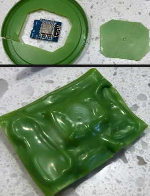
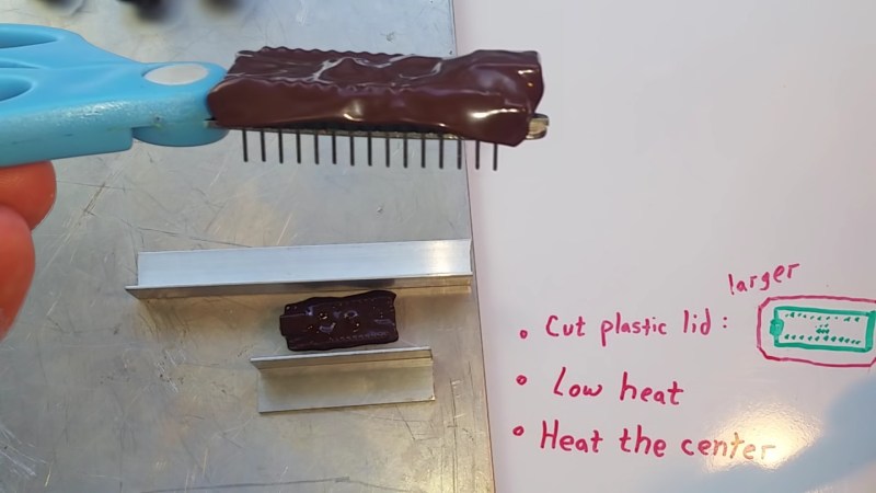
An errant wire snipping across the wrong electrical pins spells the release of your magic smoke. Even if you are lucky, stray parts are the root of boundless malfunctions from disruptive to deadly. [TheRainHarvester] shares his trick for covering an Arduino Nano with some scrap plastic most of us have sitting in the recycling bin. The video is also after the break. He calls this potting, but we would argue it is a custom-made cover.
The hack is to cut a bit of plastic from food container lids, often HDPE or plastic #2. Trim a piece of it a tad larger than your unprotected board, and find a way to hold it in place so you can blast it with a heat gun. When we try this at one of our Hackaday remote labs and apply a dab of hot glue between the board and some green plastic it works well. The video suggests a metal jig which would be logical when making more than one. YouTube commenter and tip submitter [Keith o] suggests a vacuum former for a tighter fit, and we wouldn’t mind seeing custom window cutouts for access to critical board segments such as DIP switches or trimmers.
We understand why shorted wires are a problem, especially when you daisy-chain three power supplies as happened in one of [TheRainHarvester]’s previous videos.


Awesome tip, definitely something to save away for later.
That first picture resembled something like a choco-duino .. ;)
I thought it was a Turduino.
“It’s starting to look like a TRIPLE-duino!”
It’s a Baby Ruth.
It’s no big deal!
I used to do something similar with DVD cases. Worked a treat.
I wonder if one shouldn’t worry about heat buildup when running.
Heat buildup on an Arduino is not much an issue…
HDPE very easily builds up a large static charge. Probably not the best option for protecting electronics.
i imagine children rubbing a balloon on my amega48pa
most the arduino pins have a 200k pullup or less
and the plastic is touching a few ground pins
the static should be dissipated into the power supply before it forms
Touching the GND pins does not help. HDPE is an extremely good insulator. There will not be any static dissipation. OTOH it also prevents pins from ES discharges.
would a primary layer of shrink tubing help (as isolation)? or does it suffer from the same problems with static charges?
I’d be a little concerned about the heat causing components to migrate. I regularly use a similar heat gun to remove surface-mount components from boards. It might be better to use a defunct board to melt the plastic over, and then pop it off and put it on the target board.
I feel like the heat to melt/form the plastic is a lot lower (and shielded by the plastic) than the heat needed to melt the solder.
Agreed. The heat is being used to heat the plastic, which is shielding the components below it. If those are getting THAT hot then I’d say “you’re doing it wrong.” After all, it said “heat gun” not “atmospheric re-entry”.
Using a vacuum forming machine to pull the plastic down nice and tight would look really good.
try this process upside down
heat plastic chip first then press the arudino down onto the plastic
Interesting, but I can’t think of any scenario where this would be preferable to conformal coating.
Strange, I can’t think of many situations where it wouldn’t.
Conformal coating is far superior, will keep out dust and moisture too, this will not. The silicone stuff works good because you can peel it off to rework if you have to
at 3:03 you can see that the plastic is not really touching the pcb. So yea it protects from something touching physically touching the top of the pcb but not form dirt or moisture. If you buy a can of conformal coating, you pay some money (not really expansive) but your much saver. It might not “look as save” because it is transparent but it keeps away almost everything aside from hard mechanical stresses.
DIY feasibility is the main one that comes to mind.
A conformal coating is a superior outcome in more or less all respects(the plastic shell might be a trifle better at keeping physical impacts from shearing off small passives); but is rather inferior in the “can be done quickly with tools you have and plastic probably waiting for pick-up in your garage right now” test.
I’d be more than a trifle skeptical if I saw this in an actual manufactured product; but ease of execution counts for a lot in the ‘improvements for your personal one-off projects’ department.
Hmmm… How about putting a sheet of thin plastic with a high melting temp on (kinetic?) sand in a pot. Lay the HDPE on top of it. Once it gets soft enough, just push the part down into it. The sand will be fluid enough to ‘flow’ into the contour while being solid enough to resist some of the pressure.
Most of the time I case my arduinos in a small prescription pill bottle, and I drill a hole in the lid for wires or to add a power plug.
Other times I buy a battery case for 8 AA batteries then tear out the dividers on half of it, so my arduino runs on 4 batteries and the other space is for the arduino itself.
way to make something harder without really improving anything. i’m gonna stick to using a strip of masking tape or hot melt glue when i need to guard against stray contact. the masking tape is easy to apply/remove and will prevent contact, while the hot melt glue has the bonus of also stabilizing any free-standing wires.
A cheap project box will (look and) perform better. With this method as the board heats and cools, gaps will form and humidity/moisture/dirt will become an issue. Epoxy (and rubber) potting protects the device against the elements as well as offer some level of security.
So the impedance of rf traces is determined by many things including the materials on top and bottom of the copper signal traces. The PCB antenna was designed to have fr-4 or similar underneath and air on the bottom. Laying plastic on top of the PCB trace antenna or other rf traces or components will likely reduce performance. Leave at least maybe 1mm or space on top of the rf stuff and keep the plastic elevated off the board in rf areas