The average FDM 3D printer is not so different from your garden variety laser cutter. They’re often both Cartesian-coordinate based machines, but with different numbers of axes and mounting different tools. As [Gosse Adema] shows, turning a 3D printer into a laser cutter can actually be a remarkably easy job.
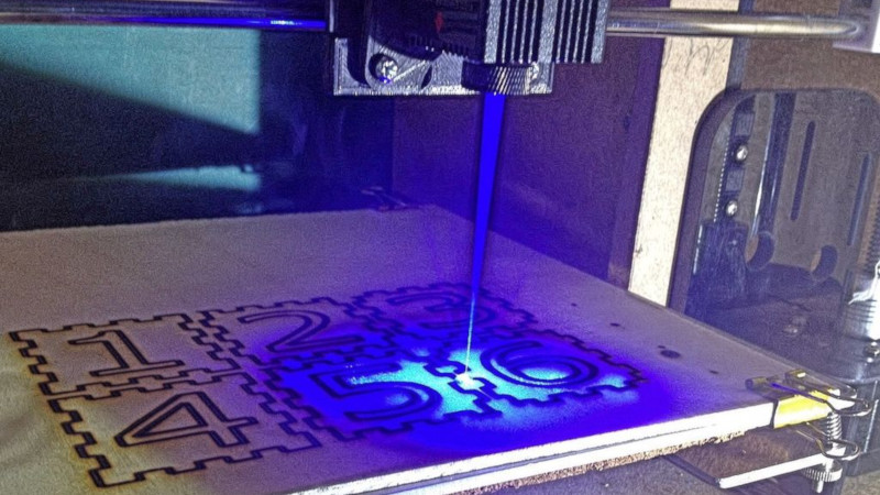
The build starts with an Anet A8 3D printer. It’s an affordable model at the lower end of the FDM printer market, making it accessible to a broad range of makers. With the help of some 3D printed brackets, it’s possible to replace the extruder assembly with a laser instead, allowing the device to cut and engrave various materials.
[Gosse] went with a 5500 mW diode laser, which allows for the cutting and engraving of wood, some plastics and even fabrics. Unlike a dedicated laser cutter there are no safety interlocks and no enclosure, so it’s important to wear goggles when the device is operating. Some tinkering with G-Code is required to get things up and running, but it’s a small price to pay to get a laser cutter on your workbench.
We’ve seen [Gosse]’s 3D printer experiments before, with the Anet A8 serving well as a PCB milling machine.


is it really that hard to modify 3d printing firmware to include interlocks and the necessary safety systems?
These are not firmware, these are hardware elements.
Even 5000W solid state laser can bring a lot of damage (like setting a house on fire). So all these conversions must be done extremely carefully and used with caution.
Yep. The one I sell has a tilt switch so that it only shoots downwards. At least it should help with not losing an eye.
That’s useless. Even the reflected light is enough for eye damage. It only takes milliwatts of power to damage the eye.
Sure, all of the modifications here were hardware based specifically so that there would be no modification of the firmware (using fan PWM to control the laser duty cycle) but there are opensource 3d printing firmware that could be modified to provide for such interlocks. From some quick searching the A8 can use the Marlin firmware, so it shouldn’t be that hard to implement safety features in firmware. Even if you didn’t want to use that firmware there should be some way of creating a hardware circuit that would trip a safety stop using some part now unused on the printer (say the bed thermal protections).
My point is that if you are converting a 3d printer to be a laser cutter/engraver with a diode laser then it shouldn’t be that hard to implement the interlocks and safety systems that would prevent the majority of possible calamity?
You can’t design interlocks in software. That’s useless. What is meant by an interlock in the case of a laser cutter is a physical switch that either prevents you from turning the laser on or cuts the power as soon as the enclosure/working volume is opened/penetrated.
The problem that the laser could be accidentally turned on by the firmware not knowing that there is a laser instead of a fan is the least of the issues. These kinds of devices *must* be in an opaque enclosure because even an accidental scattered reflection will damage your (or your family member’s who happened to poke their face in the door at the wrong time) eyes. Or it could heat something up until it catches fire.
Also the fume/smoke ventilation is an issue that is much easier to solve if the device is enclosed.
Unfortunately the internet is full of clueless people and companies wanting to profit from them, selling unsafe equipment to any bozo that can pay 200-300 bucks. Even a 500mW bluray diode will blind you in an instant, this “hack” is using a 5W module. That the guy is relying on the Chinese laser protection glasses is also telling – trusting one’s eyes to the cheapest piece of plastic with who knows what properties instead of buying properly certified safety glasses.
“You can’t design interlocks in software.” I completely understand why a hardware Interlock is always the best solution but isn’t some sort of software safety system better than no system?
and in either way, my point still stands. It shouldn’t be that hard to implement either one (hardware interlock or software safety systems) should it? An opaque enclosure with a door switch that when closed completes the power loop for the diode seems like the simplest solution and quite probably the cheapest.
“selling unsafe equipment to any bozo” any equipment or tools are unsafe to the majority of people, but what is the other option? do we require every purchase to be verified with a safety training cert? Could you imagine having to go to a hammer safety course? lol i get that there is a difference between a class 4 laser and a hammer but once you start regulating purchases it begs the question where do you draw the line because there will be lots of people and companies who will take the new regulations and find some way to take advantage of them for personal profit at the expense of others (as is human nature now a days).
To consistently make my meta point: I think that hackaday should keep posting these “hacks” but should clearly and adamantly criticize the safety aspect of it and also provide some information on proper safety in these “articles”.
A reminder why you don’t do software safety interlocks: https://hackaday.com/2015/10/26/killed-by-a-machine-the-therac-25/
Indeed, a “door open” switch doesn’t have much relevance if your 3D printer has no door, nor even any enclosure at all.
You still technically have an enclosure, it’s the room it’s in, so the “door open” switch should be on the door into the room.
We are experimenting with 200W fibre lasers at work and the development room had to have all it’s windows blanked out and an interlocked door switch that disables the laser whenever the door is open. A big red flashing light indicates when the laser is active and all inside must wear the appropriate laser goggles.
In the case of this project, it’s all very well the user wearing goggles but what if your child or a pet walks into the room at the wrong moment? What’s going to protect them?
This is a very good article in general, the only problem with it is how it describes the electrical connections of the laser module to a very custom Anet board. More widely used RAMPS and MKS Gen may need slightly different approach. FAN output is controlled in a way that both wires are at 12V potential when the FAN is off. SO it is kind of inverted 12V PWM output. Red wire is always at 12V potential, while black wire is shorted to ground with MOSFET by normal PWM signal from ATMega (low-side switch circuit). Knowledge of this is the main difficulty of this conversion. People suggest to use inverting transistor circuitry, someone came up with an idea to use an optocoupler. The simplest way I’ve figured out is to solder a TTL wire from laser module directly to the GATE pin of the FAN MOSFET on my MKS board.
Here is my example of Delta conversion: https://www.thingiverse.com/thing:2791931
Magnetic joints allow quick and easy swamping between print-head and laser-module, but do reduce the maximum speed of printing (can’t not hold up at high speed). And just for fun – some alternative use: https://youtu.be/jnHQpG4gfi0
I kinda feel like you didn’t read the source (or article) at all and want to just flex your knowledge. The article doesn’t mention at all the connections.
1. There is nothing “custom” about the builders Anet board.
2. The builder is using the PWM output of the fan to control the fan, exactly as you describe.
It’s as close to plug and play as you can get. i have the 5.5W, but I put mine on my Ox CNC via the PWM of my TinyG. The biggest issue is making sure your PWM voltage and the laser are the same voltage otherwise you will need a logic converter.
Kinda feels like you were trying to take the opportunity to say “I did it better” when in fact you did it no differently.
I did read and like the article in general\(what I’ve admitted in my first words)
But found very confusing the electrical part of it. It contradicts to my knowledge of how that works.
There are some words about problem of direct connection of fan output to 12V laser module based on assumptions of power consumption (incorrect by the way, the power is not limited by currently connected device, but rather width of traces on PCB, power supply and MOSFET used in switching circuitry). Some laser modules don’t have a dedicated TTL pin, but can be PWM modulated with its power supply. In fact this article references to the laser module with “TTL required” option.
There is no mentioning that the FAN output is actually inverted PWM signal (when fan is OFF – both wires are at 12V potential). If you look on the given schematic of PWM/FAN connection (resistor divider with an image of red Anet board) – that will not work as TTL input to control laser intensity on RAMPs and MKS Gen boards (like I have on both of my printers). So that is why I’ve assumed that Anet uses custom schematic with high-side switch (12V FAN PWM output is not inverted). But if this assumption is wrong – we have a problem. Resistor divider will produce 12V potential when the FAN is OFF. Turning ON the laser module by default with a possibility of destroying TTL input due to over-voltage.
That’s actually addressed further down in the Instructable. But it is misleading, since the first part suggests that you’re good with the resistor divider.
Oh, wow.
My bad, actually stopped scrolling on the first G-code examples.
There are going to be alot of people with eye damage from this sort of thing. Maybe someone could do a writeup on laser safety that each of these articles could link to. Too many people out there just go build something they saw on a youtube video or blog without actually understanding what they are doing. At these power levels even secondary reflections can cause permanent irreversible eye damage. Used to be that lasers had a high barrier to entry that only the people who know what they are doing had them. Now anyone with a little $ can get a high powered laser capable of blinding someone, and them use them in unsafe ways while being ignorant of the hazards involved.
Human nature has a way working those things out.
An injured person contacts a Personal Injury law firm. The law firm finds an area with a gullible jury pool, and they set out to sue anybody, even remotely connected to the laser or apparatus. The law firm charges 60-70% commission if the lawsuit is successful, and they start a multi-million (or more) dollar lawsuit.
If they are successful, a bunch of millionaire wannabes jump on the bandwagon.
Soon, lasers have a high entry barrier again.
(tongue-in-cheek)
Good luck suing a random Chinese vendor selling these modules on AliExpress where most of this stuff comes from.
There is a good reason why Cubiio Kickstarter had a massive problem because they discovered that if they actually want to sell their engraver in Europe/USA they would need to completely redesign the device to enclose it. Otherwise it would be confiscated on import as unsafe. The original had a laser module on a small tripod, totally unprotected. And that is a much weaker laser.
Lawyers almost always charge 1/3 of the settlement, not “60-70%” but it’s good to know that you don’t know what you’re talking about and aren’t ashamed of sharing that with the world.
http://robots-everywhere.com/re_wiki/pub/web/Main.LCheapo.html Open source laser driver design right here :)
When I built a laser add-on for my cnc mill, I used a switching LED driver to power it. (I work in LED driver IC design.) They’re very high efficiency, low cost, and there are lots of places that provide free design software that’ll produce a schematic from your vin/vout/ILED requirements, and even some that’ll also create a BOM with links to electronics supply companies so you just click buy and the whole kit shows up on your doorstep, sans PCB.
It’s easier to make a standalone machine. You don’t need height, you need X and Y travel and you 100% need to use a fireproof light-tight enclosure, and proper safety goggles as a precaution. Lasers can destroy your vision at the speed of light. A class IV laser diode can easily pierce your eyelid and destroy parts of your retina, permanently blinding you. Is your vision really worth saving $90 to bolt it to your 3d printer instead of making your own properly enclosed device?
You can see (and make your own!) my design here if you are curious. https://www.thingiverse.com/thing:1396503
You don’t NEED height adjustment, but it’s nice to have. There’s a reason we’ve seen so many Z axis add-ons for the K40. So if you’ve got a 3 axis machine you can modify, you might as well take advantage of it.
That doesn’t change the fact it should still be enclosed, of course. But there’s plenty of enclosed 3D printers that could be used as donor machines.
Sure… the laser *might* burn my retinas to crisps. But they’ll grow back. Right?
This is insanely irresponsible to post this project the risk of injury is too high
Please be safe all. Proper ventilation, proper enclosure, and if you’ve built it yourself everyone in the room should be wearing laser eye protection. Just because you did the math and there’s perfectly no leaks doesn’t mean someone didn’t tape down the safety switch because they had something big they wanted to cut. Lasers are awesome, and because they are awesome they must be treated with respect.
I’m deaf. If I’m blinded I will commit suicide. Seriously. But only after I have attempted to ensure the perp does not pass on their defective genes/memes to any offspring.
There’s a reason laser labs traditionally have a sign “do not look at laser with remaining eye”.
This is one where a bit more cash gets you a lot more product. unless you want to do both 3D printing and laser cutting in the same space, like a hi tech shopsmith. On the flip side, figure you are in for over $200 for a 3D printer kit and the laser diode and power supply. Doubling that gets you 8 times the laser and a metal enclosure, and the fan and stuff to vent the smoke and fumes. However if you are apartment bound or what not, it is very much like a hi tech shopsmith. If you added better motors to the X and Y axis you could also make a collar to hold a dermal drill and have a little router as well. The low end 3D printers are limited to what, about 8×8″ so you don’t have a huge playground but it could be neat to have all 3 items in one box. I wonder if you made a knife chuck if you could not add cutting vinyl to it’s tricks.
BTW, my cheepo 3D printers live in wooden boxes, but it would not be hard to line the inside with colored sheet metal flashing.
5000W? 5 kilo watts? Yep that will burn your house down, and that of the rest of the neighborhood ;)
If you think this is cheap, I used lasers from dvd drives and stuck colored gels (from the lighting department) onto safety goggles as protection ;) I still have both remaining eyes working perfectly, no worries!
I used the fan pwm to control the power. At 1% it was nice to setup where the origin is without the need of safety glasses. The laser did scatter a bit when cutting foam, I just resisted the urge to look at it :)
The biggest challenge was to get software to get the gcode. I used ink scape and its gcode plugin, changed the code so that it used the fan pwm to turn the laser on and off during travel moves. Most cam software has a scripting language you can change like HSM works and Vectric Aspire. That way you can export or process for the device you have.
I’d like to add a higher power laser module to either my 3D printer (300x300mm enclosed build space) or cnc (700x450mm non enclosed but in a separate room that can be vented) or build a new machine for it when I’ve got a bigger house to house all of my DIY projects :)
5 Watts.
5W is easily in the “put it in a box so that only the webcam goes blind” power level for me. Especially with moving reflective metal parts around where you’d like to terminate the beam.
It doesn’t need to be fancy. Getting the laser surrounded by something opaque is half the battle. The rest is foolproofing. And ventilation.
Foolproofing is no easy task, since we always completely underestimate how foolish we can be. Still, some is better than none. Except when having some makes us think we’re safe and can be more foolish. People are weird.