Electric motors are easy to make; remember those experiments with wire-wrapped nails? But what’s easy to make is often hard to engineer, and making a motor that’s small, light, and powerful can be difficult. [Carl Bugeja] however is not one to back down from a challenge, and his tiny “jigsaw” PCB motor is the latest result of his motor-building experiments.
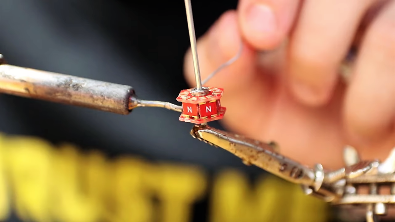
We’re used to seeing brushless PCB motors from [Carl], but mainly of the axial-flux variety, wherein the stator coils are arranged so their magnetic lines of force are parallel to the motor’s shaft – his tiny PCB motors are a great example of this geometry. While those can be completely printed, they’re far from optimal. So, [Carl] started looking at ways to make a radial-flux PCB motor. His design has six six-layer PCB coils soldered perpendicular to a hexagonal end plate. The end plate has traces to connect the coils in a star configuration, and together with a matching top plate, they provide support for tiny bearings. The rotor meanwhile is a 3D-printed cube with press-fit neodymium magnets. Check out the build in the video below.
Connected to an ESC, the motor works decently, but not spectacularly. [Carl] admits that more tweaking is in order, and we have little doubt he’ll keep optimizing the design. We like the look of this, and we’re keen to see it improved.


Why not make the single board with two boards? Stack them like this:
Board
—Bearing—
Rotator
—Bearing—
Board
In theory this would double the output but also not add much extra production requirements, keeping things simple.
Good idea, but I wonder if adding more coils would eventually go beyond what the tiny magnets on the rotor would be able to handle.
My comment was a response to the statement at about 6:35 “this design has only one bearing which can sometimes cause wobble”.
Even if the second board doesn’t have any coils, it could still have a second bearing. But if you do add coils on the second board, why can’t you double up on the magnets as well? Basically a mirror copy of what is already built in the single board.
Two boards with two sets of magnets is still less complicated than the 18 or so parts (also the soldering) of the jigsaw design.
Hmm, nice tiny thing applicable to Lego perhaps – nice way to start to teach primary school kids physics and electrical theory, thanks for post :-)
Interesting!
When I read the title though, I though t it was talking about a motor from a jigsaw. E.g. https://www.builders.co.za/Tools/Power-Tools/Saws/DIY-Jigsaws/c/DIY%20Jigsaws
Somehow missed the puzzle link.
You and me both… so the entire read-through I was thinking the motor was reciprocating.
Is it me or one lateral piece is in the wrong orientation (shouldn’t it be N S N S N S ?)