Machinists like to live on the edge, but they always want to know precisely where it is. If you’ve watched any machining videos (*cough*) then you’ve seen heavy use of digital readouts on machines. A “DRO” (as the cool kids call them) is a little computer that knows where the slides are, and thus where your cutter is on the piece. However, there’s a catch. DROs don’t know the absolute position of the spindle, they know the relative position of it. The bottom line is that a DRO is just a fancier version of the graduated scales on the hand wheels. The key difference is that the DRO doesn’t suffer from backlash, because it is measuring the slides directly (via glass scales similar to your digital caliper) rather than inferring position from rotations of the leadscrews. With traditional hand wheels, you have to compensate for backlash every time you change direction, and a DRO saves you from that (among other convenience features).
The point is that, whether old school or new, you still only get a relative coordinate system on your part. You need to establish an origin somehow. A useful way to do this is to set an origin at one corner of the part, based on its physical edges. How do you tell the DRO (or hand wheels) where the edges are? Enter the edge finder.
Precision Beyond Measure
The humble edge finder is one of those tools that are so commonplace in manual machining that everyone has forgotten how clever they are. It’s just a shaft with a precision ground stub on the bottom of it that is free to float around laterally (with some spring tension on it). This shaft is of a precise (and known) diameter — typically something conveniently halved like 200 thou or 6mm. You’ll see why this matters in a moment.
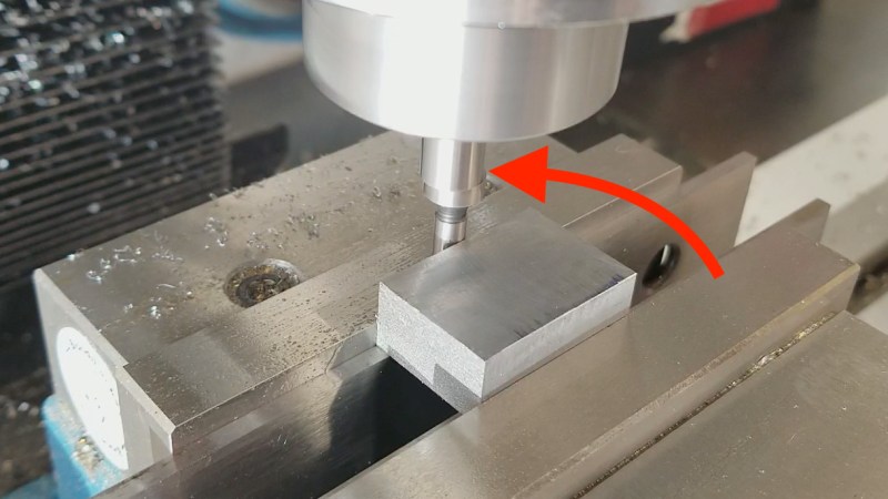
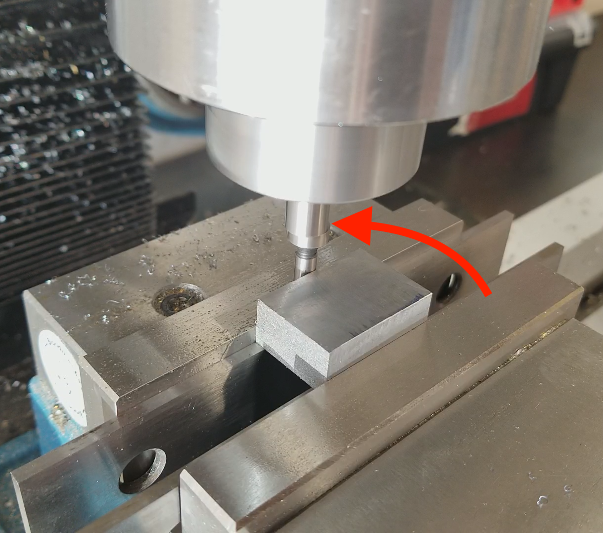
When chucked in the mill, the edge finder’s stub will wobble around like crazy, because it’s free to do so. To use it, you run the spindle at a moderate-to-high RPM (say 1000) and bring the wobbling end up to the workpiece. As the edge finder contacts the part, the wobbling end will become more and more concentric with the arbor of the tool.
So here’s the trick, and what makes the device so clever. In principle, when the wobbling end is precisely touching the surface, the edge finder tool will be running perfectly concentric. However that’s pretty much impossible to see by eye. If it’s close-but-not-quite concentric, you won’t be able to tell. To get around that, the spring tension holding the wobbling end is calibrated such that the spinning surface will “grab” the part and gain traction right as it becomes concentric, causing it to kick off to the side as it tries to roll along the surface. This is visible as the wobbling end “kicking-over” to one side. There is some technique here to get a perfect reading, because if you continue cranking the table past that kick-over moment, your reading won’t be precise. However, with proper technique, this very simple device is extremely precise and repeatable.
Going Halfsies From Tip to Spindle
Once you’ve found that edge, you know that the edge of the tool and the edge of the material are in the same place. However, what you want is for the center of the tool (and thus your spindle) to be on that edge. This step is easy, because as we said earlier, the diameter of the edge finder’s tip is known. Simply raise the tool clear of the work, and continue moving in that direction by the radius of the tool (as shown on your hand wheel or DRO). You can now set your DRO (or hand wheel) to 0 in that dimension and repeat in the other dimension. You’ve now got an origin in a known location, and by extension a coordinate system across the whole part. There are many types of edge finders (including electronic ones commonly used in CNC), but the basic cylindrical wobbling type is common, inexpensive, and precise. Three things that machinists love!
Avoid Tolerance Stacking
One final note — when making your own mechanical drawings, it’s always helpful to pick one corner of each surface from which to mark all your dimensions and locations. Edge finding is a main reason why. If all your numbers are relative to the same corner, the machinist only has to edge-find once, and there will be less accumulated error from resetting the origin. Either that, or the machinist has to do math to recalibrate all the numbers you gave to be relative to the same place. Both scenarios will make said machinist angry. Help heal the generations-old rift between engineers and machinists by minding your origin. If you don’t, expect to someday find a chuck key on the wrong side of your broken window.


My dad was one of the old school Machinist. I couldn’t find a buyer for his tools.
You tried? that’s so sad.
I certainly expect my daughter to throw out a lot of my junk but I hope she will keep the good stuff and use it herself!
My wife told me; “A week after you’re gone, it all goes out on the sidewalk, $0.25 each!”
B^)
Do u still have any of them
Randy
Yeah, my wife is going to have to deal with a load of tools that I have if I go feet first before she does. Hopefully I’ll have a bit of warning and can give a bunch of it away before the scammers show up.
Do you still have them?
Finally a case where a short embedded video or animated gif would actually add value…. And nothing. Not even a link.
+1
What he said.
I also needed that video, because this article is so full of machinist jargon that I couldn’t understand it. What is “kicking-over”? What happens to the tool when it “becomes concentric”?
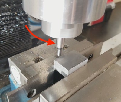
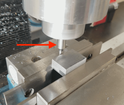
Three arrows all pointing to the same thing. That’s all you get.
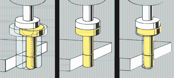
It ends up looking like the two shafts -the part held in the spindle (the part of the mill that spins and holds your tool) and the part touching your workpiece- slowly transition from being two separate pieces (a stationary bit and a wobbly bit) to being a single piece…..then suddenly the once wobbly bit moves again making the shafts look separate again….that’s when you are at your edge.
Thank you :)
If you do it once, you’ll know. The edge finder starts out with the tip running out, visibly, at 1200 rpm or so. As you get closer with the running out tip touching the part, you feed in slowly, and it runs closer and closer to not “running out”, you’re pushing it towards being concentric. The part held in the chuck or collet is pretty close to running straight and true, the .200 dia. tip is swinging in an arc, “out of true”. Feeding in, it gets closer and closer, when you are .100 away from the true location of the edge, the tip will be running close to perfect. If you go maybe .0003 past that .100, the tip will “kick over”, you’ll see it, it will move maybe .030 off center, (I’ve never measured it, but it is very visible). I don’t know how else to explain it. I hope it’s clearer now. But maybe it isn’t.
An example: (go to 3:30 if impatient)
https://www.youtube.com/watch?v=Y8Bt8yigBiU
I’m sure I’ve seen this old tony cover it too, but this video was perfect. Thanks.
That makes a lot more sense now!
Basically, the center finder has to be pushed out of the way because it can’t occupy the same space as the part. You can tell you’ve hit that point when it goes from looking fine to oscillating/vibrating because it is then trying to occupy the same space as the part.
I’ve seen it on This Old Tony as well, but never really understood how it worked until now.
Quick tip, if you want to link to a youtube video at a specific time, just add “?t=210” to the end of the url, where 210 is the offset in seconds.
eg:
https://www.youtube.com/watch?v=Y8Bt8yigBiU?t=210
well that didn’t work :(
The edge finder can also be used to “roughly” find the center of a round part, on a milling machine. Before installing an indicator, to fine tune the precise center. Just move one axis at a time, zero on one side, move to the opposite side, subtract have of the distance. Then repeat for the other axis. Learned this trick, almost 30 years ago.
My understanding has always been that an edgefinder relies on instability to kick out the moment it goes past concentric. But, because the instability transition is so sharp, past concentric == concentric within the tolerances one cares about. This seems more plausible than the spring tension being calibrated to kick out at the concentric point. However, I’d love to find an authoritative reference that definitively explains how this works.
doesn’t really matter as long as you it the same way on both sides
But we’re Machinists. We have no higher authority, and we know everything,, just ask us, we’ll tell you that we know everything (this applies to every machinist I’ve ever known, at least those that are worth a ffffffff…).
it may be way more expensive, but a haimer 3d indicator is more accurate, faster, and its scale is already adjusted for the size of the ball on the end, so 0 is 0. Played with a wiggler a bit in my manual days, but would have sprung for the haimer had I known about it then (or maybe its just really new?). Now I mostly use a renishaw probe or the haimer…
$450 for a Haimer indicator, vs $10-$25 for a Starrett or Browne & Sharpe edge finder, that doesn’t get any closer than that stone age edge finder? Uh, no. And were talking manuals here, not CNC. And your good old tenths indicator to verify. Send it.
Umm… Are you sure? As I understand it, the offset edge finder as described in the HaD post will find the center of the spindle, a fixed indicator will not. For example if your chuck or collet is off-center with respect to the spindle, a fixed indicator will always be off center as well. Therefore it will always give you erroneous edge detection even if the error is so small you can’t see or feel it (vibration). The offset edge finder does not have this problem. When the offset edge finder kicks out, it has detected the center of the spindle even if the chuck or collet is slightly off center. Go to around 4:00 minutes in this video and the gentleman explains how this works:
How to select the right Edge Finder for you
https://www.youtube.com/watch?v=bga7y4infIo
Hello, trying to leave a reply and CANNOT! Please Fix this comment system mess HaD.
Yet here’s your reply…..
The edge finder works because, no two objects can occupy the same space! You cannot fit a 1” pin in a 1” hole either. Physics 101. Al, manual/CNC Machinist for 35 years. (I still use an edge finder)
I find it easier to just key in the actual offset into the DRO. So once you get kick over you just type in “-.1000” (or 0.1000 if you’re on the + side of the axis) into the DRO. Then the zero is set.
4 places to the right of the decimal point?
DROs? What’s that? :-D
Back when I learned how to machine, our shop instructors will put a cover over the DROs when we were first learning. On Bridgeport and Bridgeport clone machines, the leads on the X Y table lead screws were 10 TPI. You “reset” the graduated ring on the lead screw to 0 when your dial indicator kicks out. Because it’a s a 10 TPI screw, each revolution on the hand wheel advances the table 0.100″, which is why they made the edge finder 0.200″ diameter (or 0.100″ radius).
I think you have your numbers slightly off but the right idea. Every bridgeport and clone I’ve ever used moves the table .200 for a full turn of the x or y handwheel. That would make them 5 TPI. I always set my dials to .100 on the handwheel so that when I spin them half way around they are on zero. I have a 1956 j head that I still use weekly. We have 3 cnc mills in our shop but the old manual bridgeport still gets utilized. If nothing else, it makes an awesome drill press.
“With traditional hand wheels, you have to compensate for backlash every time you change direction, and a DRO saves you from that (among other convenience features).”
Well, you still have to deal with backlash. You will still generally want to come into a dimension against the cut so that the lead screw is loaded against the nut in the correct direction not to drift out while cutting.
“This shaft is of a precise (and known) diameter — typically something conveniently halved like 200 thou or 6mm.”
Measure it with a micrometer, and you’ll find that it’s slightly over the nominal diameter, by just enough that when it “kicks”, you are centered by half the nominal diameter. So you are right about what to do — it’s just important to know that by running it until it kicks, you should adjust by the nominal radius, not by the radius as measured with a micrometer. I’ve seen several of us hobbyists confused by that.
And then throw in climb milling (I always climb cut, if the machine can handle it), and that backlash will sssuuuuuuuccccckkkkk the cutter in, most ot the time I’ll drag the lock a bit
There is very convenient shop kink – but works olny in X Achse, and only in machines with two handwheels in that axis ;)