Soldering is best done under magnification. Parts become ever smaller and eyes get weaker, so even if you don’t need magnification now, you will. [Makzumi] didn’t want to shell out $400 or more for a good microscope so he hacked one from some cheap binoculars from the toy section on Amazon.
A lot of magnifiers aren’t really good for soldering because the distance between the work and the lens isn’t very large. The hacked ‘scope has about 4 inches of working distance, which is plenty of room to stick some solder and a hot iron under there. The resulting magnification is about 12 or 15X and he claims that the cell phone pictures he’s included aren’t as good as really looking through the eyepieces yourself.
The project requires two toy binoculars. The ones linked are 26mm 2.5X foldable ones that cost under $5 each. One of them will get ripped apart for lenses. The other will form the main eyepieces of the scope. You’ll also need a little PVC pipe, some epoxy, and some wood to make a stand.
Since the modified binoculars will be looking at things very close, you have to cut into them to make them look almost cross-eyed. It appears the whole thing might cost $20 and it appears to work well. We’ve looked at other solutions like the Dino-Lite. There are also many cheap USB microscopes around.


This seems suitable for the third world. I’ll stick a $60 USB microscope and a tablet.
Well, I hope you and your chosen tools are very happy with each other, but I for one applaud the author and his work.
Do you have a scope to reccomend?
I like the Aomekie usb microscope. Looks like a tube and comes with stand. You can find it on amazon. The simple tube shape makes it easy to adapt with 3d printed holders.
Here’s the one I have. It’s a bit more expensive but works really nice. It has an HDMI output that goes straight to a spare monitor (no tablet or computer needed).
Link: https://www.amazon.com/gp/product/B01MF5KMBL/ref=ppx_yo_dt_b_search_asin_title?ie=UTF8&psc=1
Do you have a particular model in mind that’d allow you a 4” working space in between a PCB and a lens?
Just a thought- I do watch restoration with a cheap 2x barlow lens over a 90x stereo microscope from AMScope. Cheapest well made microscopes I have seen.
I get about 8″ or so underneath for holding up 5A tweezers for hairspring manipulation- and you can get a post mount stand type that you xan secure to any 1.00″ rod you can find, or other mounts like this main article one.
Their stuff can be cheap, but its nice. Not 60$, but not 1000$ either. Not affiliated- just like their stuff. Might work for you.
Pure optics, without electronic signal procesing give you less latency. Something I really appreciate while soldering. I would not want to have to solder with such a USB camera.
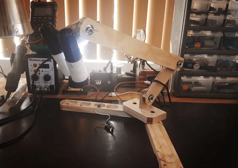
fun project, seems very workable. Love the stand design as it allows for many adjustments and appears to have a stable base without obstructing the working area.
This project proves to show that with some common sense and imagination and creativity you can go pretty far.
The USB microscope and tablet trick is nice but isn’t perfect either. Sometimes you just need something that looks and feels like a microscope and fully optical without lag, glare or pixelation, this project does just that. Well done.
2nd grade Dad already had me “helping” in his electronics shack, and taught. It was all tubes and point to point wiring back then. 8th grade was teaching me cobol and had me coding on punch cards he would run at work. First computer I got my hands on at work was magnetic core and I really wanted that TTY with punch tape later on but thankfully cassette came along and took over. I’ve stuck with it all, it’s been a great hobby alongside the auto mechanics Dad also taught, and all bundled together made for a great career. As a hobby at home I was doing my own boards with DATAK and sharpie, and later direct transfer using a laser printer. First computer was built was an 1802 and rushed to get the wife and show her it’s working, that first program just blinked an LED. I can still hear her screaming at me “You spent a hundred dollars to just make a light blink?!!! I did manage to dodge the broom….
But its all getting too small. I’ve microscopes, binocular as well as electronic, and it’s manageable but not at all optimal and the writing on the wall says I can’t go any smaller but it’s just going to keep going that way, and that is going to happen to all of us and go way beyond the problems we have now.
All the theory still works… and it’s still all great fun… but in 20 or 30 years you’re going to need quite a set of lab equipment just to build a project.
Sure has come a long way since my 5th Grade Science Fair when used an NE-2, resistor, capacitor, and 90V battery to make an NE-2 blink. The battery looked like a giant 9V. Friend grabbed it and thought he could touch his tongue to it just like a 9V. He literally did a standing still backflip! It resulted in my spending the day in the office.
Now… those are “My Years”. And if you listened you can get a hint of what “Your Years” are likely to be. I’m still having a blast, but I’m working off a huge bench supply of “old tech” parts.
Best of Luck. Wonderful Hobby!
Thanks man I’m a milenial (‘94) and I throughly enjoyed this passage. A man after my own heart. Hope your days all, are filled with happy hacking
The project deals with the two key issues which are essential to the hands on aspect of fine pitch work.
1. Stereo – the depth perception makes all the difference to effective work. Even with a lab full of whizzy video microscopes and large LCD panels I still use the old stereo microscope for hand soldering. If I wasn’t so tight I would have a Mantis as they are the bees knees.
2. Zero lag – Even with my ageing nerves it still amazes me as to how I can lose the shakes when I can see what I am doing. The body seems to naturally servo the motion relative to what it can see. This doesn’t work if there is lag in the visual path.
Happy memories Biomed, I too grew up in my Dad’s workshop with electronics being a part of life from day one. The most heavily reinforced memory being blown off the chair when I found the crack in the insulated shaft of the screwdriver while pulling arcs of the top of a 6CM5 ;-). Later on I went on to find out that an interesting side effect of aircraft HF’s still having valves was that power supplies could hold a significant charge on the caps for long enough to get from the aircraft back to the workshop only to catch out young players carelessly having a probe around.
For a bunch of locals we all got started in 78 with the EA 2650 mini. Crazy amounts of time and money to make a few LED’s blink with code entered on a row of switches, literarily bit by bit. Fair to say that when the trash80, with a cassette interface, arrived it was well received as was the assembler.
Fortunately 7 years later we got to have a C compiler when the sweetest computer of all time was released ( Forever an Amiga 1000 tragic ;-). Interestingly it first appeared with a system written in B, from BCPL, before it transitioned to C. A fully multi-tasking graphics based operating system on a single 360K floppy. It was so far ahead of the IBM clones and the Macs in the day, shame Commodore managed to squander the opportunity. Happy days.
Cheers
This is a neat build. I rather wish he’d designed a 3D printed scope head. That would make building another one of these a lot simpler. I love the idea of just using cheap optics from other products. Nice work!
I wonder if you could design a stereo inspection microscope head around the lenses that come out of cheap binoculars/scopes on eBay? That might be a very cool hack.
That said, I bought a cheap pair of stereo dental loupes, search “3.5x 420mm dental loupe” on eBay. They work really nicely once you get used to moving your head around to focus. Not as good as a real microscope, but 1/10 the cost and the optics are actually pretty good.
Wonder if I could cannibalize them into a nice stand?
A usb scope and tablet comes in as a poor second to this honestly. Mind you I have a nice Olympus stereo microscope that I use. Working in stereo with real optics is a whole different thing than looking at a screen. Nice project this.
great hack
Hey, as someone who teaches SMD assembly and rework occasionally, please please please don’t use a USB microscope or anything with a screen. They’re awful. Instead, get a “toy” stereomicroscope. They do exist, and they’re pretty cheap (most expensive I’ve seen is ~$50). They sell them for looking at rocks. They’re not like a high-end stereo scope in that the viewing area is relatively small and the magnification is too damn high (you want 5-10x at most, and the toy scopes are generally 20x) but they have zero delay, which is all you care about when doing placement. For inspection, the USB scopes are okay, but for actually doing any work under the microscope they are awful. The latency messes with your hand-eye coordination and you lose the benefits of magnification. The toy stereo scopes are equivalent to this binocular hack, except they also come with adjustable eye-to-eye distance (which this hack sadly breaks in the modification).
If you are moving quickly while doing rework, you are doing it wrong. If you are using a soldering iron for SMD assembly, you are doing it wrong.
Why not use a soldring iron for replacement of single or a few SMD components?
Of course, for assembly of a whole board solder paste and reflow is much better. Even if the paste stencil is cut from overhead transparency mylar film, because the available laser cutter has not enough power for metal. Even if the vacuum pinzette is built from a syringe, needle, some tubing and a car central locking airpump.
And even if the reflow oven is the cheapest pizza-toaster available :-)
Been there, done that :-)
But for repair or patching the iron is quite OK. You do not have to reflow-bake the whole board. Except if the IC has a GND pad, then you need hot air.
Nice cost effective resourceful build! I’m fighting the urge to try this and am thinking when I’m at the thrift shop I’ll have similar urges when I see binoculars now.
Thought this was a fun project, so ordered some of the binoculars, printed this holder by Mikezs: https://www.thingiverse.com/thing:3955880 and laser-cut a very rough stand for it….and it’s surprisingly good! A useful stereoscopic microscope for under £5, and very little work to make it….I got lucky as the interpupillary distance (IPD) of the 3d model matched mine at 60mm. The depth of field is pretty shallow, but I can use it with just ambient light, so a good trade off. I’m having a play with some aperture reduction – but it’s good enough as is.