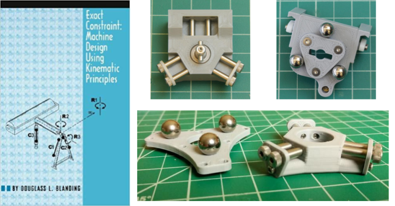
Surely, if you’re reading this website you’ve teased the thought of building your own 3D printer. I certainly did. But from my years of repeated rebuilds of my homebrew laser cutter, I learned one thing: machine design is hard, and parts cost money. Rather than jump the gun and start iterating on a few machine builds like I’ve done before, I thought I’d try to tease out the founding principles of what makes a rock-solid machine. Along the way, I discovered this book: Exact Constraint: Machine Design Using Kinematic Principles by Douglass L. Blanding.
This book is a casual but thorough introduction to the design of machines using the method of exact constraint. This methodology invites us to carefully assess how parts connect and move relative to each other. Rather than exclusively relying on precision parts, like linear guides or bearings, to limit a machine’s degrees of freedom, this book shows us a means of restricting degrees of freedom by looking at the basic kinematic connections between parts. By doing so, we can save ourselves cost by using precision rails and bearings only in the places where absolutely necessary.
 While this promise might seem abstract, consider the movements made by a 3D printer. Many styles of this machine rely on motor-driven movement along three orthogonal axes: X, Y, and Z. We usually restrict individual motor movement to a single axis by constraining it using a precision part, like a linear rod or rail. However, the details of how we physically constrain the motor’s movements using these parts is a non-trivial task. Overconstrain the axis, and it will either bind or wiggle. Underconstrain it, and it may translate or twist in unwanted directions. Properly constraining a machine’s degrees of freedom is a fundamental aspect of building a solid machine. This is the core subject of the book: how to join these precision parts together in a way that leads to precision movement only in the directions that we want them.
Part of what makes this book so fantastic is that it makes no heavy expectations about prior knowledge to pick up the basics, although be prepared to draw some diagrams. Concepts are unfolded in a generous step-by-step fashion with well-diagrammed examples. As you progress, the training wheels come loose, and examples become less-heavily decorated with annotations. In this sense, the book is extremely coherent as subsequent chapters build off ideas from the previous. While this may sound daunting, don’t fret! The entire book is only about 140 pages in length.
Beyond the methods introduced in the book, the author peppers it with anecdotal wisdom that clearly comes from the mindset of a seasoned machine designer. Blanding spares no expense at reintroducing familiar parts and coloring them with context. No longer will you look at a screw the same way. And Blanding is also generous with showcasing real-world examples of these principles from fields like robotics and optics.
This book was first published in 1999, and the concepts have been well-known by optics and instrument designers for over a century. But with 3D printer building now in the mainstream and with precision parts now available on Amazon, this methodology has never been more relevant. It is a founding language for the machine designer. That said, if you’re a seasoned mechanical engineer already aware of the method of exact constraint, perhaps this book isn’t for you, and you can likely get what you need to know from this open-courseware pdf. But if you’ve ever poked through a forum and seen someone reply “hey, your printer is overconstrained,” they’re referring to the method of exact constraint, and this book is just what you need. By thumbing through this book, you too can develop a mindset that enables you to definitively decide when to use a coupling, a linear rail, or a bushing. You too can speak the language of the machine designer.
The spellbooks of hardware that sit on my shelf are few-and-far-between. These are books that promise you no heavy prior knowledge to pick up a foundation of the basics and walk away with something new. While these are rare, Exact Constraint is one of them. It’s a foundation for conversing with other machine designers. I’ve begun applying these principles to my latest 3D printer build, and it has transformed the quality of my prints. With this spellbook I hope that you too can invoke the power of this unsung art and put these ideas into practice in your next machine.


Apparently this is a textbook used in college classes, or at least Amazon thinks it is. I hope this article doesn’t affect the supply resulting in some students not getting their copies!
Anyway, it seems to vary, mostly between about $80 and $100. This place is selling the PDF (I assume they have the rights) for $22.46.
https://kissly.net/book/AD51C254675814BA02AD?utm_source=ps17&utm_medium=laucrislide.ga&utm_campaign=fnom&x=525467
I wondered that too. Our survey says perhaps note:
I have a question for the expert, I learned mechanics in France, and I struggle a bit with vocabulary. In France Kinematics is a “science”, and system are classified by the statism: isostatic (perfectly constrained), hyperstatic (over constrained), and hypostatic (some movement is possible). I don’t think this kind of vocabulary is used in English, where “kinematics” is often used for our “isostatic”. What is the proper terminology?
Kinematics in English is used to meant the study of motion. As such, the way it’s used would apply to hypostatic cases, where a mechanism is capable of movement. Kinematics would be the means by which you plot what motion is, and is not, possible for a given mechanism.
Typical division in the US at the university level: Kinematics vs Dynamics vs Statics. Kinematic forms deal with motion, and involve underconstrained components (at least one degree of freedom), though a realized system is generally fully constrained. Kinematics courses also consider the fully constrained cases, but analysis of the overconstrained cases is not the focus, if touched at all. Forces and spacial properties are considered, and energy may be, but stress sd strain in the individual elements would not be (that is statics).
US physics text books have sections on “statics”, which are non-moving systems. It is all forces and static friction or “stiction”. Then comes “Dynamics” or “Kinematics” with forces on moving objects and their motions. Like kinema/cinema for motion I guess. Kinescope, etc.
In France statics is the science of things moving at constant speed (including zero).
ΣF=0 and so on. Same everywhere pretty much.
Only people in California get cancer…
Most products only cause cancer if used in California.
I want to add that we had specific symbols for each kind of joint to do the analysis: https://docplayer.fr/docs-images/45/23408448/images/page_10.jpg I don’t see that in the English language world.
Looks like an interesting book, but it costs 100$ and is not available in electronic format.
Here, is a scan but better than anything https://gofile.io/?c=0UDKQN
You saint!
The hero we need!
Upload does not exist…
Thank you so much!
I saw it for $77 but same sentiment– OUCH !!
Another similar book, that goes into some detail about constraints and degrees of freedom, is “Making Things Move DIY Mechanisms for Inventors, Hobbyists, and Artists” by Dustyn Roberts, https://www.amazon.com/Making-Mechanisms-Inventors-Hobbyists-Artists/dp/0071741674
I found it really useful and a little cheaper, although I sure do like Blanding’s book as well.
Designing Cost efficient mechanisms by Lawrence Kamm
One of my first engineering internship assignments was recreating a company’s entire product line in Inventor. Back then Inventor was horribly unstable and slow. By necessity, I had to be perfectly disciplined in use of constraints to prevent assemblies from blowing apart and losing dozens of hours of productivity. The philosophy of perfectly constrained designs has paid off handsomely in the intervening 20 years in almost everything I touch as a mechanical engineer and computer scientist. This should be part of ABET’s accreditation requirements for engineering degrees.
I have been looking for a book specifically on this topic for some time, perhaps in a similar area, though at a higher level and more specific focus.
Foundations of Mechanical Accuracy by Moore is another one of these so-called spellbooks, in that it addresses where basic exact mechanical constraints and accuracy come from in milling machinery, made to an exceptional standard by Moore Tools. It would be overkill for 3D printer design, but I’m looking to build custom machinery.
I only mention this as I ordered a copy from them today, and may add this in to the mix now as a basic primer before I dive deep into that.
Nice find!
Is that Moore as in Moore & Wright?
Moore as in Moore Tools, builders of some of the finest jig grinders money can buy.
Only $5001 on Amazon, nice!
I’ve been studying the science of exact constraint, like the author of this post, to build precision machines. I’d like to second what he wrote about its utility, and add some of my own insights.
For a theory accurate to nanometers, there is shockingly little math involved (diagrams hide its differential geometry and tensor algebra). The fundamental equation of exact constraint is 6 = C + DOF, where C is the # of constraints (linearly independent force vectors) between 2+ solid bodies, and DOF stands for degrees of freedom. If your kinematic system has 4 solid bodies, and you desire 2 DOFs, and say 2 DOFs are very small (like with a turned part, rotating, where the machine is in ~the same kinematic state throughout the part’s rotation), then you need to engineer 4*6 – 2 desired – 2 ignored = 20 independent force vectors. Success with exact constraint comes to those who can, with a single nesting force vector, generate equal force vectors between all parts, in all machine states. The reward is a kinematic system with nanometer repeatability — even with sloppy machining! The other major kinematic method, the Law of Elastic Averaging (which is how ballscrews or LMU linear bearings achieve repeatability) relies on precision machining, for instance.
Like all actually-useful sciences, exact constraint was discovered in the factory, by workers. The last chapter of the book is about its moment of conception, dealing with webbing problems on the Kodak film production line, in the 1960s when the science advanced past JC Maxwell’s lab notebook poems.
The science of exact constraint encourages good engineering practice in four ways. The first way is minimizing part count. Every part adds 6 new DOFs to your kinematic system. Every ball bearing, shaft, rolling rail, etc, is another 6. Most systems only ask for 1, 2, or 3 DOFs — it is an extreme engineering challenge designing force vectors for 20 parts, to finally tally up to only 2 DOFs. The second is related: when you perform an exact constraint analysis, subtracting nesting force vectors from the sum of all DOFs, you often find you are way over-DOF’d. But (especially rotational DOFs) can be shrunk down, so while a part may be in a different kinematic state, your overall system is approximately in the same state, as if the DOF did not exist. A ball bearing rotated 30 degrees is about the same as one rotated 78 degrees. Put another way, the difference between desired DOFs and actual, is equal to the number of tight tolerances, like your concentricity or distance callouts. When you are chasing nanometer precision, part costs can balloon exponentially — so minimize part count! Some micro-DOFs are cheaper than others, like the 3 unremovable DOFs per high-precision ball bearing. But under the electron microscope, the ‘mountains’ on even a precision ball bearing surface will affect repeatability. The third benefit is more philosophical, but exact constraint is a *relation* between parts. It forces the engineer to endure the difficult task of understanding the kinematic interaction between *all* parts of the machine, instead of silo’ing one part at a time. A fourth comes from the ‘tactile’ nature of constraint-hunting. You can feel, and audibly hear, in the click-click of parts tapping against each other, how many constraints a part has adopted from another. So your kinematic designs are quickly tested: it encourages experiment, by making the experiments simple. Apply the nesting force vector, then count the contact points!
One insight I had came trying to answer: why 6? 6 is the sum of our universe’s 3 translational DOFs (X, Y, Z) and three rotational DOFs (three ‘axes’ of rotation in cross-product interpretations). The insight came by asking, why do 2D systems have 3 DOFs, the sum of X, Y, and 1 rotation? Why the jump from 1 rotation in 2D space, to 3 in 3D? And in 1D systems, 0? I noticed the series 0, 1, 3 are the first three triangular numbers. And triangular numbers can be generated as sums of all linearly independent combinations of 2 items (here, vectors): 1D has zero, 2D has XY, 3D has XY, XZ, YZ. Then 4D space should have 6: XY, XZ, XU, YZ, YU, ZU (this is true!), 5D space 10… In fact, you can ‘read off’ the rotational DOFs from Pascal’s triangle: it’s the 3rd diagonal. In our 3D universe, the 4th row of Pascal’s triangle, the actual DOF number (the sum of the row) is 8, but we ignore 2: the first number, the change in the scalar space (1 meter we assume is equal to 1 meter, meaning we ignore gravity waves), and the last number, XYZ, the map of all internal particles in a solid body to each other — bending, torsion, flex. We hand-wave this away by saying, exact constraint is a theory of solid bodies. Specifically, it is a theory of 2D manifolds, the interactions of curvature on surface manifolds, when the distances between points on multiple manifolds = 0.
I post about exact constraint with other workers on a communist forum, to better understand our labors. If you would like to read more about the geometrical basis of this theory: https://rhizzone.net/forum/topic/14538/ The science of Marxism is still the only social science not based on torturing statistics to death, capable of explaining the large-scale motions of human society. There is a disturbing amount of militarism on hackaday which, I hope, those of us who use our hands for a living, will choose to not work in service of. Us technical intelligentsia do ourselves no favors aiding the racist class that steals from the world’s poor, the US military (as Ben Franklin put it: merchants cheat, and armies steal — we call the class that steals for its food the ‘lumpen’, German for scum).
Hmmm… Not sure how that last paragraph relates to this article’s topic. I guess your train of thought wasn’t exactly constrained.
Just a content warning. Hackaday, in addition to being a great resource on DIY, features a disturbing number of non-DIY posts supporting the US military. Most links this wouldn’t matter, but I’m aware of the audience here. Nationalistic readers might find the way we talk about these types, at the link to exact constraint studies and mathematical studies, to be disturbing. Hopefully some readers dream of a better world.
Exact constraint can be put in mathematical terms — it’s a function of surface geometry, 2-manifolds. A machinist might be familiar with a common exact constraint mechanism, a cylinder in a vee, with 4 points of contact, 6-4=2 DOFs, rotating and sliding along the vee block. To explain how curvature changes the # of contact points, imagine the vee block’s base being gradually filled in, like it’s 3 sides of an octagon, instead of a square. When the inside radius of the octagon, falls below the radius of the cylinder, those 4 constraints halve to 2, and the cylinder’s DOFs double to 4: another rotation and translation. Constraints double and halve, when the ratio of curvatures between the manifolds, curv1/curv2, flits > and < than 1. The US military exterminated an entire continent's peoples in one of the greatest crimes in human history, massacres in every US town, turned the continent into an Indian graveyard. That 2 2-manifolds can have a maximum of 6 points of contact, is a very interesting differential geometry result, IMO! A "constraint" is a shared point between two manifolds (if there are multiple shared points in the neighborhood, then the manifolds intersect, zero points and there is no contact).
I've developed a new function algebra to study these 2-manifolds (but it generalizes to n-manifolds), and have developed a 2-DOF rail system for precision tool placement in a plane, with only 4 micro-DOFs, which works as this science predicts! I don't mean to boast, just publicize: I'll update that link on the forum, about this stuff shortly.
This is hilarious. You made up that hackaday is vehemently militaristic so you could post communist propaganda? Of all the things you find in comments sections…
https://hackaday.com/2019/09/05/ham-radio-company-wins-big/
https://hackaday.com/2019/09/04/eagle-reborn-f-15-simulator-from-a-wreck/
https://hackaday.com/2019/09/03/3d-printing-may-be-the-key-to-practical-scramjets/
This is just the past week, about one militaristic post per day. I don’t think it’s hilarious at all! And of those three, the only actual project is the simulator — the other two are war company press releases. You get one chance to lead a good life, you forfeit it designing hardware for the US military, or normalizing military propaganda here, between artsy LED circuits and 3D printer designs. We swim in this stuff in the US, so it’s not too shocking that it washed right past you.
I’m the last person to wave the American flag in favor of the military industrial complex, but tou are making a big leap from “appreciating the design involved in military hardware” to “hackaday supports the troops!” But then again all roads lead to communism in your posts so I guess that makes sense.
Alright man. I’d rather talk about kinematics — are you up on the theory? Did you see the illustrations in the link I posted? Did they clarify, or confuse?
I was trying to show how, degrees of freedom are gained or lost, exactly where a secondary manifold becomes non-differentiable, the secondary manifold made by tracing a particle in a solid body, over every possible position. If you integrate the position of one part against another, what were once smooth manifolds, gain kinks and cusps, in the exact locations DOFs are gained or lost.
I now get that, this is only true in simple systems like spheres, where normal vectors intersect. Now I’m trying to generalize it.
Did you want to talk about that, or hackaday’s nationalistic politics? (they really only post super cool military hardware by the US war industry, out of hundreds of potential world militaries to admire. Dunno if you’ve gotten recruited, but the MIC advertises to technical workers in the same way, I believe your distinction is without difference).
Uh…overwhelmed here and I can’t tell if you’re trolling.
Why are these sentences slipped in randomly between 2 on topic sentences:
“The US military exterminated an entire continent’s peoples in one of the greatest crimes in human history, massacres in every US town, turned the continent into an Indian graveyard.”
It’s not your ideology that I have a problem with; though I don’t agree with it. It’s the absurd lengths you will go to to cram it down our throats that I have a problem with.
To clarify, I am not referring to those two sentences when I say that I disagree with your beliefs. I am referring to your beliefs about Marxism.
I’m sorry, did you have any comments or insights about this science? I understand the US nationalism of hackaday attracts a certain type, but I hope to extend an olive branch to citizens of the post-holocaust state. I know we can look past our differences for the sake of scientific discovery, like past generations of US colonists found it in their hearts to work with Soviets. I wrote a lot about this science: did you have *any* comments?
Toyotathon,
I find this to be a blog written from American prospective.
There doesn’t seem to be any political or militaristic bias on Hackaday to me. Its just based in a country where more info is published and available on US military tech.
One thing I have found I like about here is that there doesn’t seem to be any political bias- there is a bias only towards something that is technologically revolutionary, no matter what that form takes.
For the record I am personally very liberal, but I work in the very Devil’s Den as it were of conservative types. Hackaday is an open mind to me, unambiguously, since the founding. That’s just my take, and I like that it is unbiased just Tech awesomeness
You’re all dummies for even engaging with someone like this.
“…The US military exterminated an entire continent’s peoples in one of the greatest crimes in human history…”
This is selective history. Typical hate Whitey and very racist in assuming that no one else is responsible for anything or has any agency at all. It’s all Whitey in charge of everything(to them), no one else’s actions matter. The vast large majority of Indians were killed off by disease that came from the “world Island” of Asia, Europe, etc that they had no immunity to. After that there was vast lands empty that the Indians mostly wandered around in the western portions. You leave out the part where the Indians would attack farmers. Killing all the babies, gruesomely torturing the Men to death, enslaving and raping the Women and Children. Eventually to stop this the US Army forced them to move to one area so they could keep track of them or if they refused, chased them down and killed them. “If” the Indians had decided to live peacefully it would have never happened. The ones that did settle down lived. You can’t expect people to not become extremely violent if you go around murdering their Men, babies and enslaving and raping the Women and Children.
Marxism in practice is sadly based on torturing it’s citizens to death instead…
Not really geography explains everything
This book was written by and makes references to ex-Kodak engineers, and it was required reading when I joined their glasscutting operation (now part of L3Harris) that makes space telescopes. This is very uselful stuff for anyone interested in making optical supports.
I’m an optomechanical guy. Have any other favorite books of this caliber?
Most of my other spellbooks on similar subjects are either general engineering texts or binders of notes on hyper-specific topics. Blanding does a good job making an accessible dive into a narrow topic, which is likely why Exact Constraint got published.
One binder that was always kept close to Blanding’s book had notes on flexure design and stick-slip-jam theory, pertaining to actually constructing the theoretical 1-DOF constraints described in the book, or at least making good approximations.
I was thinking looking at the three spheres in that picture, it had to be a very precision support of something that needed a perfectly defined plane. I dont know what it is- but I would guess it is a support for optical lens lapping, or CMM probes, given my very strange background.
When i was in school as a tool and die maker we had to purchase a german book, Feinwerkelemente. i still use it today. Its as good or even better, but we had to translate it… [without google becuase goggle popped up some 6 years later]
https://www.amazon.de/Feinwerkelemente-Verbindungen-Baugruppen-Mikromechanik-neubearbeitete/dp/3446160531
Can you post the other textbooks you used?
I’m a tool and die machinist that followed a strange and multilingual route myself…
Working in learning technical swiss french and German
A more comprehensive book that includes some kinematic design is “Building Scientific Apparatus”
https://play.google.com/books/reader?id=yuGHu2HpeIkC&hl=en&pg=GBS.PP1.w.1.0.1.187.0.1
FWIW, hundreds of libraries have copies of this book: https://www.worldcat.org/search?q=978-0-521-87858-6&qt=owc_search
Something to look into if you’re building a machine to do an operation in a 3 dimensional space, if all it does in 3D is follow one precise path back and forth all the time.
Replace an XYZ axis machine with a single dimensional track that’s bent as needed to move the tool through the space it needs to travel. This has been done on machines that apply inserts and remove parts from injection molding machines.
Instead of a 3 axis gantry with its several motors and drive systems, they use a single axis track with a 90 degree curve. The tool grabs an insert off the supply belt beside the machine then rolls on the track, turning the corner to be properly oriented to put the insert in the mold. After the shot, a similar bent single axis runs a grabber in and out to remove the item from the mold and deposit it into a belt on the other side of the molding machine.
Two drive motors instead of six, and the motion is precisely constrained in 2 axes while being able to adjust position along the bent-linear axis. The track could be bent in different directions to create 3D like rotations to apply tools to a workpiece or present a workpiece in different orientations to multiple tools.
I can tell you right now while I appreciate your out of the box thinking, practically speaking, it would be near impossible to create the kind of system 4 actual CNC you describe, in a lasting and repeatable, verifyable accuracy configuration.
Your application of blow molding die technology is intriguing and admirable, but realistically unfeasible, in short due to higher level technologies required to create a dimensionaly accurate and stable curved or multicurved axis in this fashion. Sometimes the limiting factor being conventional Cartesian is not the problem or the limitation- sometimes the basis for all accurate measurements being based of of variations of linear systems (aka gauge blocks, lightwaves, etc) is.
It could be done as an art piece within machine technology, but never a mass production item, based on standards of measurement that would dictate its accuracy- at least as things exist currently
FWIW, many libraries have a copy of it: https://www.worldcat.org/title/exact-constraint-machine-design-using-kinematic-principles/oclc/878738335
Better link: https://www.worldcat.org/search?q=9780791800850&qt=results_page
How interesting! There’s an article (in Russian) that makes exactly the same point:
https://pravmash.ru/osnovnaya-statya-o-probleme-samoustanavlivaemosti/
For example, the author reviews a slider that in which two pairs of bushings slide on two parallel rails. He proves this is overconstraining, and suggests a pair of bushings on one rail and a simple support on another (a bunch of flatbed scanners I’ve disassembled are actually that way!).