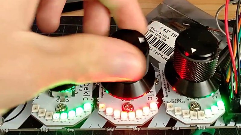
While the “M” in MIDI stands for “musical”, it’s possible to use this standard for other things as well. [s-ol] has been working on a VJ setup (mixing video instead of music) using various potentiometer-based hardware and MIDI to interface everything together. After becoming frustrated with drift in the potentiometers, he set out to outfit the entire rig with custom-built encoders.
[s-ol] designed the rotary-encoder based boards around an FPGA. It monitors the encoder for changes, controls eight RGB LEDs per knob, and even does capacitive touch sensing on the aluminum knob itself. The FPGA communicates via SPI with an Arduino master controller which communicates to a PC using a serial interface. This is [s-ol]’s first time diving into an FPGA project and it looks like he hit it out of the park!.
Even if you’re not mixing video or music, these encoders might be useful to any project where a standard analog potentiometer isn’t accurate or precise enough, or if you just need something that can dial into a specific value quickly. Potentiometers fall short in many different ways, but if you don’t want to replace them you might modify potentiometers to suit your purposes.


Be really interested to see the verilog source…
Ditto.
So it’s multiple USB rotary knobs, using FPGA instead of USB?
Pretty sure you can have multiple encoders talking to a single Arduino. Adding the LEDs is a nice touch, however.
https://www.amazon.com/DROK-Lossless-Computer-Controller-Adjuster/dp/B01MV411BR
I don’t think they are USB encoders. One of the issues of hooking up rotary encoders directly to a Arduino is the overhead it requires. Using a stand alone asic or cheap cpld is really the way to go. Fpgas are usually going to be overkill.
Oh, unless the microcontroller has enough channels of onboard hardware for the task.
yes, the FPGAs here are way overkill! Not only is putting *an* FPGA there overkill, the UP5K is also way overpowered in the iCE40 series, it just happens to be the only one in the series that is available in a QFN package (everything else is either BGA or dual-row QFN, which wouldn’t have worked out with cheap PCB processes, or the fact that this was also my first time doing reflow soldering).
I was trying with an ATTiny 417 before, which was just a tad too complicated to get to work with the very limited amount of pins and peripherals and a ‘no compromises’ design where it would be able to poll the encoder using interrupts while maintaining LED refresh rate and be responsive over SPI – at least I couldn’t do it, it’s probably possible. If I redesign the board I might very well go back to a small MCU solution.
One of the things that makes encoders great is the precision you can get with them. And if you don’t debounce them they act very imprecisely. (Sometimes jumping and on the least convenient time). I suspect that he is using the FPGA to do more than just driving the LEDs. I know you can denounce in software but I have had great results with hardware debouncing with a CD40106 (that I got from an article here). I’ve only read about FPGAs but implementing some kind of debounce would be easy for the person that knows how to use them. And with one FPGA he might simplify the board design.
Amazing upgrade would be an intertia- (accel-?) based 10-turn pot. Where turning fast would move through the range quickly, but slow movement would be at 10x precision. Or something…user experience should be refined over that ;-). Or, use a rotary encoder that can be push-pulled, or even button-pressed to switch between low and hi-res modes. This seems an excellent integration of multiple high-touch features difficult to make otherwise: bravo!
That’s why the knobs can be individually programmed, I haven’t finished their firmwares yet – I’m working on individual ones for knobs that operate in an infinite range (dashed LED ring shows offset but no absolute value), knobs in a unipolar range (as pictured above), knobs with a bipolar range (-1 to 1). I will keep this in mind and play around with inertia as well, although I am not sure whether the 24 steps per turn are enough to get a good reading on that.
Solid looking knobs (took 3 attempts to make that statement not dirty). Anyone know where they were sourced?
I’ve sourced many robust knobs over the years, but I’ve not kept in touch with the sources so I don’t know whether their knobs remain solid or have been softened by the years.
Sourced via alibaba, if you want specifics you can reach out to me via ‘contact’ atop my website, linked above.
Will you be posting a more detailed build for those encoders? I would really like more details.
I have a rotary encoder Gist example in Verilog if your interested (Note: there are pictures and diagrams at the bottom.)
https://gist.github.com/wdevore/8b1c0d7ac769b59e955cb390b0a03134
Actually, I have several where each does something different with a LED bargraph.
https://gist.github.com/wdevore/014845dfbfa9572c7d770ce3a4dcf8b3
For those who needs PSoC library for rotary encoders:
https://community.cypress.com/thread/30654