When the Raspberry Pi 3 Model B+ was announced in March of 2018, one of its new features was the ability to be (more easily) powered via Power-over-Ethernet (PoE), with an official PoE HAT for the low price of just twenty-one USA bucks. The thing also almost worked as intended the first time around. But to some people this just isn’t good enough, resulting in [Albert David] putting out a solution he calls “poor man’s PoE” together for about two bucks.
His solution makes it extra cheap by using so-called passive PoE, which injects a voltage onto the conductors of the network cable being used for PoE, without bothering with any kind of handshake. In general this is considered to be a very reliable (albeit non-standard) form of PoE that works great until something goes up in smoke. It’s also ridiculously cheap, with a PoE injector adapter (RJ-45 plug & 2.1×5.5 mm power jack to RJ-45 jack) going for about 80 cents, and a DC-DC buck converter that can handle the input of 12V for about 50 cents.
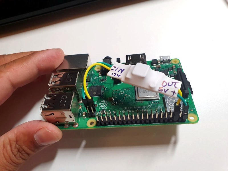
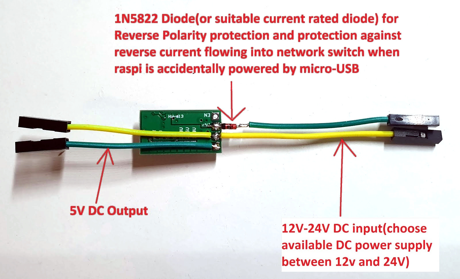 The rest of the $2 budget is mostly spent on wiring and heatshrink, resulting in a very compact PoE solution that plugs straight into the PoE header on the Raspberry Pi 3 board, with the buck converter outputs going into the ground and +5V pins on the Raspberry Pi’s GPIO header.
A fancier solution would implement any of the standard PoE protocols to do the work of negotiating a suitable voltage. Maybe this could be the high-tech, $5 solution featuring an MCU and a small PCB?


This looks like a simple UPS…or am I missing something?
There’s no battery, it’s just a DC-DC converter. Power comes in over the Ethernet cable. PoE stands for Power Over Ethernet.
There’s an IEEE-endorsed way of doing so, called 802.3af (also .at, .bu, .bt extensions) which involves handshaking and signature detection so the switch doesn’t accidentally provide power to a dumb device and set it on fire or something. It’s very safe, but expensive to implement.
This is the other way. It relies on the user not accidentally providing power to something that can’t handle it. On the other hand, it’s extremely cheap to implement.
ethernet is transformer isolated so dumb devices should have no problem with voltage between pairs
In theory, yes.
In practise, maybe sometimes…
Yes I have seen devices release the magic smoke after being fed Nonstandard PoE. As the article mentions, it “works great until something goes up in smoke”.
Some devices have 75ohm resistors connecting the center taps of the transformer together to reduce EMI. If you connect a passive POE source you will burn up two of these resistors, the port will work normally afterwards, albeit maybe not meeting EMC requirements. Some dumb passive PoE injectors put the voltage not between pairs, but + and – on a single pair. This will burn up the transformer in a gigabit capable port. It may work fine afterwards as a 100mbps port.
The other disadvantage is also that it can’t use high speed Ethernet (such as 1000), which requires all 8 wires. In this case some of the wires are reserved for power delivery and can’t transmit information. I was looking for a cheap solution 4-5 years ago. Cheapest I could find was external adapters for 15€. It works really nice though. There was an open project on GitHub, which was ~50€.
PoE works with up to 10g Ethernet. The data rides the DC. In fact .by uses all 4 pairs for power in some modes. I’ve done several 1gig PoE products.
With active PoE right? Not with passive PoE (that is what I meant in the context of the article).
Back in the old days, PoE was 48 volts same as phantom power for onstage sound at music shows. Same as audio phantom power, PoE runs not via the signal pair (the twisted pair), but across ‘hot’ and the earth or shield pin. It’s why you need 3 pin XLR cables for condensor mics, DI boxes, piezo pickups. Makes a helluva bang at the end of the gig when the musician unplugs and 48 volts of DC potential is briefly sent into sensitive mic preamps. Also only 48 volts goes the distance… as in 200 meters. Think voltage drop.
You can do passive gigabit poe with bunch of ceramic capacitors and few small ferrite bead inductors. Look for “mikrotik passive gigabit poe”, it’s quite cheap and compact. However if your device has center taps in ethernet transformer, you don’t even need this.
Not always true. Transformers not designed for PoE often have much too thin wire (high DC resistance) in the transformer windings, so if you try to draw much power from the center taps, you just melt the transformer. Ask me how I know!
This is also the hazard of “dumb” PoE, since some devices ground the center taps, or short them to each other.
Multi-Gigabit can have PoE+ 802.3at, Netgear MS510TXPP as example.
On the other hand, there’s sadly not much of Multi-Gigabit PoE equipment, I’m still waiting for PoE+ Access Points (because you need two cables for one AP to get full speeds at max utilization >_>)
In the enterprise space and LED lighting, there are tons of 4PPOE switches. They go all the way up to 71W, delivered to the endpoint. Many of the bigger, WiFi APs and bridges accept some form of 4PPOE. Not saying it should be this way but people are running CAT6A for lighting applications.
Who needs gigabit on a freaking rpi?!? If youre saturating a 100mbit line whatever you’re doing probably requires more than yesteryear’s roku/smart-phone overstock CPUs.
All too often it seems people put far too much faith in these little SoCs. They’re meant to be learning devices, not a wallet-hack to more processor nodes. I mean, yeah its great technology has progressed to the point that a full Linux environment will cost you little more than what you can take out of your couch. But seriously, they were never meant to replace a proper computing environment. Of course this is coming from the guy that often complains about people wasting a raspberry pi 4 on a weather station when a microcontroller built into a Bluetooth module would get the job done. To be fair though C can be a PITA to learn as a first language….
Boat life community finds them useful. Designers intent doesn’t really matter for a product, if it functions as you want it to. C isn’t that hard to learn.
Or rather – this is how the PSU on the Pee should have been made:
12-24V input and a 2.1×5.5 mm power connector.
I wouldn’t trust a PI on that buck converter. I ordered a few dozen similar ones because it were cheap but I yet to find a project to use them because:
The buck converter IC on them supposed to be a Monolithic Power one, but its just a bad clone.
The output is noisy.
The feedback voltage is totally random between units (some have 0.6, some 1.5V ) and depends on the output voltage.
There is no startup current limiting, it almost acts like a direct short from Vin to Vout at startup. Some even overshoots the target voltage by a considerable amount.
The no load current is high, in the tens of mA range.
Efficiency is well below 80% on some units.
The pot to change the output voltage is unstable, drifts on its own.
I planned to use one of them to pre-regulate a LiPoly charger IC’s input but somehow it ended up killing the charger IC after a few hours. An other one ended up drifting to 1.2V from the initially set 0.8V killing the device.
The input voltage is advertised to go up to 21V, but in reality it cant handle huge differences (21->3.3V for example), the inductor is not sized to do so.
For powering LED strips or something similar they are maybe OK, but nothing else. I ended up ordering genuine MP IC-s, and replacing the clone ones on a few of them and changing the feedback divider to fixed resistors. At least the PCB (if you dont need the powerSO8 pad) and caps are adequate.
The genuine IC-s behave totally different in a good way.
I recently mounted one inside a 24V power supply so that I could use a 12V cooling fan. I can see them being used a lot for that, running 12V fans in 24+V 3D printers and other CNC machines.
This is not PoE. At best, it could be called poe, but we prefer to call it VoE ( Volts over Ethernet ) .
PoE is a standard, with well defined voltages and currents on the cable. This practice of inserting random voltages in the cable causes much problems when the unprepared user , who doesn´t know the differences, connects his uncompliant thing to a real PoE switch. From damaged equipment, to grief having to explain to a stubborn customer why he burned his camera/phone/whatever after connecing it to that thing that was said to deliver power over ethernet.
If the guy wants to use that connected to a network cable, or (re) publish the idea on the internet , he could at least use a DC-DC module that would accept up to 50V inputs, at least.
This device shouldn’t get any voltage from an 802.3at or 802.3af (the two versions of the only real standard for PoE), unless he’s really unlucky and happens to take exactly the right amount of current to look like a 25 kΩ resistor.
That said, I’m worried about the opposite side of this: there’s now an RJ-45 jack that has 12VDC on it all the time, just waiting for someone to plug some other device into it. It’s fine for a quick hack, but I don’t like it as much as standards-compliant PoE.
I’ll also mention, there are quite cheap PoE PD adapters. Amazon was showing me a $10 one that is 802.3af-compliant, and gives you 5VDC out, perfect for powering things like Raspberry Pis.
“This is not PoE”
Yes it is. The term has been in use way longer than modern PoE exists. Stop redefining terms. It is not “PoE as standardized by …” but it is PoE. End of story.
I run my raspi3 on my 3d printer using a buck converter that gets its juice from the 3d printers power supply. its attached right to the outside of the ps’s cooling fan too, just in case it gets warm. similar in concept to that.
This is a horrible hack (i.e. when things go sideways there’ll be a lot of smoke and potentially hundreds of dollars damage to devices) and has nothing to do with PoE at all. Why not simply hook up the hodgepodge step-down converter to a 12V directly? Or here’s a crazy idea: get a real IEEE802.3af/at splitter which are available at your favourite Chinese mailorder shop for way less than $10 (100MBit/s version) or slightly above (GbE version) which nicely deliver 5V/2.4A directly at a MicroUSB connector…
Nice, Clean, Easy
10/10
I have used commercial versions of this device in my work to remotely power non POE Waps, cheep and simple, never been a problem.
What about the current draw? Can Poe really handle 3 amps?
Soldering a component like that to a wire with no strain relief will result in a broken joint. A glass body diode is also very fragile. That diode is not rated for the current you are subjecting it to, and will probably fail shorted. Those cheap converters have no protections. In my experience, the most common failure mode for them shorts the input voltage to the output… I atleast hope your Powersupply output is fused or limited at a suitable current so the entire thing doesn’t go up in flames.
This site is becoming more like ‘burn down a house a day’…
Sorry to be so nega I’ve about it, but this is bad.
simple and to the point. i like it.
– no bulk caps at the input/output of switch mode module.; Should consider caps + ferrite filters
– “dupont” connector with crap thin wire. If you ever strip one of these, you’ll know what I am talking about.
Just asking for trouble sooner or later.
PoE is the standard that describes the complicated shit that allows devices to be powered over their ethernet cable.
This is not PoE. You shouldn’t call it PoE. You can call it power-over-ethernet-cable or something but not PoE.
That would be 802.3af/at as the standard
PoE means exactly Power over Ethernet
It’s not the same thing.
Do you know if this works in Raspberry Pi 4? As it needs more specific power supply. Many Thanks
this looks like a straightforward solution but a couple questions:
1. If your switch is POE+, isn’t it putting out more like 24V? your solution is 12V–>5V
2. Where are these pins on the RPI3B board that the 12V in wires are connected to? I don’t see them on my RPI3B board