For their final project in [Bruce Land]’s class on designing with PIC32 microcontrollers, [Sujith], [Julia] and [Andrew] wanted to do something fun. And what could be more fun than bending to the electromechanical siren song of the pinball machine?
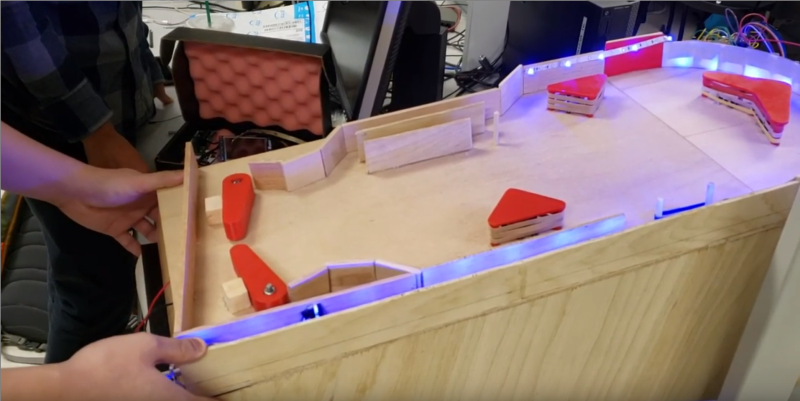
This machine looks great, and as you can see in the demo video after the break, it plays and sounds great, too. We particularly like the boomerang obstacle and the game state-driven LED strip. The more points you score, the brighter they go. We also like that this machine combines traditional scoring methods with a few really clever ones, like the boomerang target near the top and the scoring triggers made from copper tape.
The team started by designing the heart of any pinball machine, the flippers. Though we have seen car door lock actuators used in homebrew machines, the team went with traditional solenoids to drive them. Unfortunately the solenoids caused a lot of interference, but the team got around it with filter capacitors and aluminium foil Faraday cages around the wires.
If all this pinball talk has your circuits lit up, why not try making your own machine?


PICs are least preferable choice because Microchip either forces you to buy their bloody expensive compiler or use a cheaper but incredibly shoddy CCS-C “compiler”.
True. The good news is that before Microchip bought Atmel, Bruce Land’s courses used AVR and so there are both old projects and also all the lectures available using that. Since they’re donated by the company, Microchip switched the donation to PIC.
Forced? I have always written PIC code in assembler, using either my own assembler or gpasm. C on PIC would be nuts!
Just needs “The Who – Pinball Wizard” playing in the background now.
Heck yeah, sounds like this team knows a good amusement device when they see it! If any of them are reading this comment, from one pinball builder to another (look up “Undertale Pinball”) – I hope they take this idea and run with it and develop it further.
“Unfortunately the solenoids caused a lot of interference, but the team got around it with filter capacitors and aluminium foil Faraday cages around the wires.”
Solid grounding, snubber diodes, and proper wire routing would be the ideal solution. Solenoid voltage and wiring should be isolated from logic (and logic ground) except the unavoidable meeting place at the driver transistors. From experience, attempting high-frequency PWM on solenoids is also a recipe for trouble.
Glad to see Bruce Land is still there teaching that awesome, awesome class. This was my project: https://github.com/djotaku/Atmel-Web-Server Not quite as awesome as pinball.