The IBM Selectric changed typewriters as we knew them. Their distinctive ball element replaced the clunky row of typebars and made most people faster typists. When [Steve Malikoff] thought about 3D printing a type ball — colloquially known as a golf ball — it seemed like a great idea.
The problem? It just doesn’t work very well. According to [Steve], it is likely because of the low resolution of the printer. However, it isn’t clear the latitudes of the characters are correct. and there are a few other issues. It is possible that a resin printer would do better and there’s a call for someone out there to try it and report back. We are guessing a finer nozzle and very low layer height might help on an FDM printer.
Judging from the images, it looks like some of the balls do pretty well, but don’t get a full strike at the tilt angle. So it could be something else. However, it does sound like cleaning up the print so it fits is a major problem.
The Selectric was notable for several reasons — you can see an ad for the machine in the video below. The type ball meant you couldn’t jam keys. Since you didn’t have to unjam keys and you had the ribbon in a cartridge, you would have to work really hard to get ink on your fingers, even if you used the cloth ribbon instead of the arguably better carbon film ribbon. The Selectric II could even use a special tape to lift the carbon ribbon off the paper for correcting mistakes. No white-out liquid or fussing with little strips of correction paper. The fact that the ball moves means you don’t have to clear space on the side of the machine for the platen to travel back and forth.
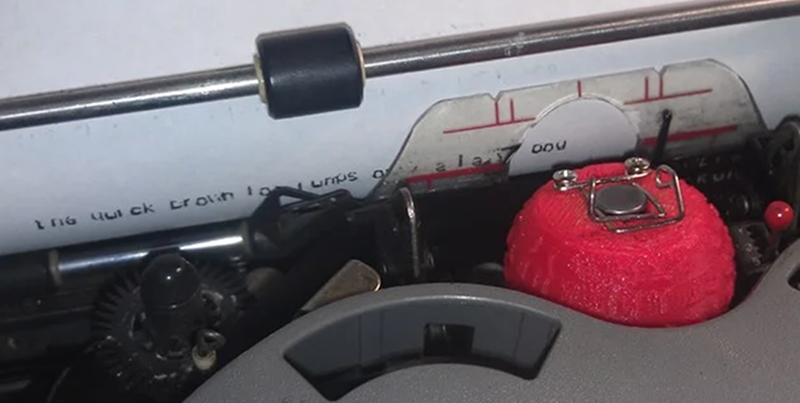
Can you help? If you have a Selectric I or II and a high-quality printer, this would be a fun project to try and report back your results to [Steve]. If you are familiar with the later issue typeballs, you might not have seen the wire clip that [Steve] uses to hold the ball in place. However, you can see them in the video ad below. More modern balls use a plastic lever that acts as a handle so even with cloth ribbons you have less chance of getting ink on your hands.
Although there were Selectrics meant to interface with a computer, you can refit any of them to do it with some work. The Selectric also has a role in one of the great techno spy stories of all time: The GUNMAN project.


As far as I recall, and it has been a very long time since I looked at one of these, the “ball” wasn’t strictly spherical, and the type had a flat face (i.e. it was not curved with the same center as the ball, but flat ata tangent to the center of the ball.
Furthermore, any wear on the ball or the mechanism would result in characters not entirely dissimilar to the print in the above example. In other words, the tolerances were reasonably, but not outrageously tight.
You might have better results, making silicone molds from existing balls, and casting in a hard epoxy or even some relatively low melting point metal. A resin printer would certainly get you better results, but you need to look at the ratio of character height to layer height to get an idea of how much better. A 10 point character is of the order of 3.5mm in height, and if your FDM printer can only give you 0,1mm resolution, the best you can hope for is about 35 layers in your 10 point character, so it is going to be pretty crude. For comparison, a good dot matrix printer might give you 24 dots worth of resolution for a similar character, and dot matrix prints are far less sharp than golfball. You probably need something of the order of 100 layers per character before you start to get good clean looking results. More is obviously better.
The type faces may have actually been slightly cylindrically concave, to match the curvature of the platen. I’m not 100% sure of this – I never placed one type-down on a flat surface to check it, and I no longer have any to look at. But certainly they were not spherical.
I haven’t looked at the scad files, but the type tests all indicate more pressure at the center of the characters than at the top and bottom, so I suspect that the maker did wrap these around a sphere.
Okay, now I’ve looked. The faces are actually flat.
They are not flat.
Look carefully at the slash mark /
They are concave.
I think you misunderstand my last comment: By “now I’ve looked”, I meant I’ve looked at the OpenSCAD code, not an actual typeball. I still don’t have one in my possession, and like I said, I would expect them to be concave. Thank you for confirming this.
There’s something weird going on with the taper of the type bodies, though: some edges have draft angles that look to be close to 45 degrees, while other edges look to be more like 10 degrees. Something not right with the geometry. As I recall, the actual typeballs had draft angles of around 30-40 degrees. Not that this is probably the cause of the poor type quality, but it would probably affect durability.
The profile of the type faces are concave.
Most visible with the / mark on larger typestyes like Orator
They are concave to match the circumference of the platen.
Platen height adjustments were critical to matching th curve of the typeface.
Selectric tech for 28 years.
Thanks Andrew, I wondered about the sphericity(?) of the ball and just went with a pure sphere. Sometime I’ll check the curvature more accurately with a DTI, if it warrants it. As for the text, my model does indeed have flat typeface surfaces. One thing that especially does not print well on a cheap printer are the detent teeth – I cleaned up a lot of them by hand with an Xacto knife.
I don’t know if this was the case for the IBM typeballs, but I had a Remington Rand Selectric typeball (either license-built or after the patent expired – the typeballs were interchangeable with IBM), and it was made of a hard plastic, then electroplated, so that the type surface was metal. There are a number of YouTube videos that show how to electroplate on plastics; they all involve spraying the plastic with some kind of conductive paint, then electroplating as usual. Probably for this, copper would be sufficient. I think this would help durability a great deal, but you’d have to very carefully finish the plastic first, so that the type surfaces are flat and smooth.
If you really, really, really want to print type, an easier and probably better way to go may be daisy wheel. These had all of the characters in the same plane, so finishing it would be a matter of making a puck that the wheel rests in to support the individual “petals”, and honing it on a piece of 600+ grit paper.
Diasy wheels were actually repairable, so long as the actual font pieces (type blocks) where intact. The splines could be repaired with care. You did need to ensure they were straight, otherwise the hammer would mash the type block and break it again.
I’d like to see someone try a 3D printed daisy wheel on a Diablo 630. One later version had a slightly longer, more powerful wheel motor to spin it a wee bit faster to up the print speed. May also have been that revision that had a V notch in the end of the hammer to work with wheels that had corresponding bumps on the back of the type arms. The purpose was to improve print quality, especially for doublestrike.
Style variations were limited to doublestrike to make a character a bit darker, bold – a second strike of the same character offset a little, and underline which spun an underline character into place to be hit.
Speed was FAST, but cut in half when applying one style. If you added the formatting commands in WordStar to print bold doublestrike underline it would bring the 630 to a crawl with 8 strikes to make one character. Probably was a way to apply bold only to the character, not the underline, to save two hits since bolding the underline would serve no useful purpose. The underline characters would blend together anyway.
I wrote a *roff printer driver for a variant a long time ago – 1/120″ was a typical horizontal offset for “bold” – worked really well as it was just enough to give you a fatter vertical “stroke” without trashing the rest of the character’s font subtleties.
Hadn’t thought about that in a long time…
I had the Juki 6100 clone. It would move 1/120th also and we would use it make very long plots with rolls of paper. You knew how many 1/120 pixels you had across the page and would use a period to make the lines. Probably took up a bunch of pixels but it still worked well. We’d print annotation sometimes or hand annotate.
But IBM Selectric typewriters do not easily adapt to daisy wheels. :)
id think the preferred failure mode would be “ball exploded”
And by the way, if you think the Selectric was IBM’s greatest invention, Google “Blickensderfer”. Patented in 1891.
Fascinating.
Thank you for that suggestion. I’ve learned something new today.
The original balls are/were metal plated (nickel??). Heavily used balls had the metal worn off on the striking surface. I imagine a non-plated one wouldn’t last very long.
Really interesting to watch one with a stroboscope. When typing, it looked like the ball was just wobbling all over the place, but at the last possible instant it would become rock stable, whack the paper, and then go back to the wild dance. The ball did not continually spin — it was positioned in tilt and rotate for each letter. Capitals were 180 degrees around but in the same “hemisphere” (north or south), so a simple half-rotation of the ball was all it took to change case.
Unlike a TTY, different letters took different amounts of time to print (depended on how far the ball had to tilt/rotate). If you wanted to go fast (i.e. not wear out the sprag clutch between the motor and the rest of the mechanism), feedback was mandatory. If you got it right, the mechanism could be kept spinning.
The only electrical parts in there were the motor and the power switch — no status feedback of any sort. Terminal versions had a set of relay/solenoids to encode tilt and rotate (simulated keypresses), but the power for the motion was purely mechanical, from the motor.
As an interesting sidenote, a standard Selectric (i.e. not a terminal version) had two-key (IIRC) rollover, and it was provided entirely mechanically. And of course, it was impossible to jam the mechanism by trying to type two characters at once.
I was never fast enough to take advantage of this, but the keyboard had a lockout mechanism so that you couldn’t press the next key until the mechanism was ready for it. Similar to Teletypes in this way. I COULD burst type on teletypes fast enough to take advantage of this lockout. What you had to do was press the key before the mechanism was ready, so that the key would actually drop at exactly the moment the mechanism was ready for it, so the clutch wouldn’t disengage. On the Teletype model 33, the printing rate was 10 characters per second, which happened to correspond to 100 WPM. I knew typists who could do 150 on the Selectric.
I’ve found the lockout mechanism kicks in when the printer is turned off, so someone mashing the keyboard whilst off won’t result in a sudden burst of characters on the paper when turned back on.
You can trip this manually by putting the Selectric up on end and it’s near the cycle clutch bail (my terminology may be wrong, but the long rod arrangement near the centre of the underside of the keyboard).
I vaguely remember that you could tap a limited subset of keys on a powered-off Selectric, then when you turned it on, all their motions would suddenly happen. Or maybe it was only the shift key. But yes, the rest of the keyboard is locked out when turned off.
Lock out was achieved by a slotted tube below the key levers containing ball bearings – when one key was depressed, it prevented another from entering the tube.
(I was a Selectric tech in a previous life)
I’ve got a pair of Selectric IIs in my basement right now, so I’m getting a kick out of this.
The correcting version seems to be working pretty well, the bog-standard one needs a bit more TLC, especially since it rattled around a bit in its case during shipping. But they’re tough, nothing broke that can’t be fixed, and it needs a new pulley hub, so I get to do the shaft removal thing to replace that.
They are fun to use, though changing balls to change fonts is a lot more time consuming than highlight-right click-italic on the PC :-) I figure for $40 apiece, I’ve bought myself hours of puzzle time. They are fun to work on, and the parts are still available from the guys who do it for a living.
There’s a Selectric group on Facebook – golfballtypewritershop
Plenty of old Selectric repairmen available who know the mechanisms (and their shortcomings) inside and out.
Selectric Manuals:
https://www.marklin-users.net/cookee_nz/hobbies/IBM/IBMSelectricAPM-Nov1980.pdf
https://www.scribd.com/document/372545238/ibm-selectric-service-manual-a
Guilty.
My dad used to be an IBM field tech for typewriters and later, PCs.
It was definitely the coolest family of pure typewriters ( not wp) ever.
I used to work on TTYs. The 33s do take differing amounts of time to position letters, just like the Selectric.
The difference here is that the 33 typewheel is much smaller than the Selectric typeball, has about 1/3 fewer characters, and a much more efficient positioning mechanism. Instead of tilt and rotate tapes, the 33 has codebars that run the width of the machine, which contact sliders from the carriage. The sliders control the lift and rotation of the typewheel, and the decoding mechanism is in the carriage, not the base, as in the Selectric. It’s a much tighter scheme with much less inertia than in the Selectric and positions the (smaller) typewheel within the 0.1 sec character time.
The “one-key only” mechanism is made up of a tube full of balls which runs the width of the keyboard, with a slot for each keyboard lever. The balls are free to move in the tube, but the sum of the space between them is such that only one keylever can fit between them. If one key is down (i.e.: through its slot and between the balls) there is no space for another, so it’s blocked by the balls.
Quite clever and works well.
SLA printer with semi-flexible resin? Siraya Tenacious as a mix-in, as example. You could get the detail and the mild “springiness” that might lend a “rubber stamp” effect. FDM isn’t a very good process when you need this level of detail and accuracy. You could run the same model in SLA and it’ll be hugely more accurate and require no post-processing.
Maybe you should try printing flat, “cartographic” character map that will fold over existing (or printed) ball. Then resolution would be less painfull because all character faces will be parallel to print layers
Well, THAT’s certainly an interesting idea. I think the challenge would be getting the characters aligned correctly when you folded it over the core form.
What about a ball covered in sockets and letterforms that plug into them?
The limiting factor is that the inside of the typeball must have enough room to accommodate the upper ball socket assembly. This is essentially a metal block/pivot with the detent banjo, and there is very little clearance between it and the inside wall, which is only about 3mm thick.
I did a detailed review of several 3D printing services and different media types, providing some idea of the quality and resolution you can expect.
Printing something like that via one of those services won’t be cheap (probably $40-100) but you’ll get something much sharper than you can print on most home 3D printers.
https://www.youtube.com/watch?v=vNoPo-UFk0A
Looking the CAD typeball I instantly remembered the ’90s news opening of an Italian TV.
Notice that the typeball in the early CGI has not mirrored characters.
Besides typeballs were molded plastic (I think PVC) and then plated with nickel. I remember that some compatibles were finished in yellow.
Woohoo!!!!
After 20-odd years reading, I made Hackaday :) :)
Thanks for everyone’s comments! Yes I am aware of the strangeness in some of the letters when trying to diverge the typeface, and that the ball and latitudes may not be quite right. Perhaps more text overlays would help.
One thing I should have done is set up a typeball on the lathe and use a DTI to determine the ball profile correctly, as well as the exact latitudes. Also AFAIK OpenSCAD doesn’t give a really accurate length for text characters, which would certainly improve the positioning on the typeball.
With the typeface not really hitting the paper properly, the zenith offset (as I called it – that nomenclature seemed to fit) can help a little, but is really a fudge factor.
There’s a LOT of room for experimentation, I’m hoping folks here might take a look at the OpenSCAD script and improve it which would be great, I really ought to put it on Github. (BTW slight typo in my surname – Malikoff with a k)
Sorry for the typo — fixed now. I have a blue Selectric II but I don’t think my current set of printers will do any better than what you have done.
Complements on the quality of your code.
Is the face of the characters on an original type element flat or curved? They look flat but that does not mean they are.
Regarding character quality, instead of testing it in the typewriter, use the type element like a rubber stamp. (Use your hand to make a character impression on paper.)
How you print the ball impacts how well the characters print. Alternately, you could try printing the ball splitting it in half along the line of the vertical. (Each half would have characters from T0, T1, T2, and T3 on them.)
You are treating “NORTHWARDS_ZENITH_OFFSET” as a constant. It is very possible that there are multiple offsets.
Your code leaves the reader to infer that you are only using integers for the NORTHWARDS_ZENITH_OFFSET. If you are, consider fractional values.
On your example photo with the red type element (it’s probably obvious but), NORTHWARDS_ZENITH_OFFSET needs to be more negative. The top of the character needs to be pushed towards the platen.
Thanks for your comment.
You have some interesting and very valid points. Perhaps it needs a zenith adjustment for each latitude?
I’ve looked at the typeball faces closely and tried to think of a way to determine if there is any concavity. The lengths of the verticals are perhaps too short to get a meaningful test with a DTI, perhaps a fine point source laser shone obliquely and projected onto a wall wilst moving parallel to the face may be enough to determine something.
Regards a rubber stamp testing, I like the idea but doing this by hand may not get a truly flat impression. But, with the magic of 3D printing, a jig could be constructed to rotate/tilt the ball before making the impression.
What about 3d scanning the ball like with one of the laser rotoscope scanners ? They sell cheaply now, in the sub $300 space.
So you can 3D print the Comic Sans typewriter ball now? I guess it can sell quite well if you bundle it with pink ribbon.
There’s many far more serious fonts to consider before such pointless trivial frivolity. Such as Klingon, Ancient (SG-1), Elvish, and The Dark Speech of Mordor (Which some say was derived from elvish comic sans, but whatevs.)
Does Elvish have uppercase/lowercase?
Comic Sans was chosen as it has a reputation of ludicrousness and some notoriety, rather than say a repop Courier New typeball.
I think that each character needs to be exactly parallel to the paper/strike surface and very small irregularities will prevent a full strike. Therefore I don’t think a ball can be used straight off a printer until resolutions like 0.01mm happen. If you really really want to make them though, I can think of a couple of approaches, and a fix…
Invent a variety of subpixel smoothing for the type areas, such that with a given exposure to acetone polishing, you’ll end up with the surface you need. Requires tight characterisation of the acetone polishing process.
Print just the ball, smooth it, rig a head mechanism to present each type location face up, stickify it with a heat gun, and plot each character on it with the 3D print head, x-y style, not raster.
And for fixing what you get now, rig print head to touch each character on a polisher/grinder wheel to surface it lightly.
Yes! You’d need two stepper motors, one to rotate the ball aka change longitude and another to tilt that motor around the center of the ball aka adjust longitude. Voila, you’ve got a 5-axis 3d printer! Then if any letters come out to too low or too high, you could adjust them with a simple y offset per row of letters, for example.
If it’s an issue with gripping the paper you could use TPU filament.
Hmmm Interesting. I have some TPU, not used it yet (got it for making RC vehicle tires) but will consider testing it. It certainly would conform to the platen curvature, whether it is too squishy (ie. its Duro too low) for the carriage’s whacking force would be something to find out.
i do not know the original designs, but in the abstract it seems a flat character rounded into the cylinder radius of the platen + paper would be optimal. With maybe slightly higher points to strike harder on the edges. The resolution of this “slightly” prolly goes beyond your FDM printer though.
I have an Anycubic Photon; SLA/DLP printing would be far better, and at $239 USD they are a bargain.
I’m thinking that to make this work you’d have to design the ball with characters that stick out further than they’re supposed to. Then design a jig possibly also 3D printed, that sits on the face of the ball, between characters, and lets you run a small file across one character at a time. Making it flat, smooth, and parallel to the correct axis of the ball. Think of a chainsaw sharpening jig.
This would solve what I see are the three biggest problems.
Resolution jaggies (smoothness), height consistency, and character flatness to the platen.
In the OpenSCAD script, the LETTER_ALTITUDE factor can be bumped up so this idea can be tried.
Not sure this has been pointed out already (couldn’t read all comments) but I think this could be done by separately printing the ball and then the character, so the latter can be planar. You’d then assemble the whole thing with glue or press-fit mechanisms….
Indeed this is possible to consider. Maybe as a radial array of gores, like a hot air balloon, adjust gore edges to allow keying and add circumferential grooves between latitudes to allow for reinforcement by Kevlar thread binding + superglue (one of my all-time favourite assembly techniques – fixes fragile things like you would not believe!)
IBM GOLF ball was a swap over from Remington who couldnt get it to work. High Speed Photography picked up the bad points and a transition from metal to metal coated plastic overcame the fatuige problem.The ball is close to 2/3 SPHERICAL,
YOU WOULD HAVE TO GET AN ORIGINAL FOR MICRO MEASUREMENTS, then metal coat as too much give in plastic alone.
The phrase adjustment (A FLY SHIT) originated with this machine. Final adjustment was tighten then hit screwdriver to move amicro millimeter, thats all it took for the ball to rotate in the opposite direction.
Thanks, that’s interesting to know. I’ve yet to set up an original typeball on the lathe and run a DTI or digital indicator over it. Copying the ball geometry as a 360 degree swept rotated spline could improve the results a lot.
I printed one up for the fun of it, and I ignored the instructions, used my ender 5, printed it in PLA, 205c, .1mm layers, 75% infill, with support touching buildplate, and getting the support material out has been terrible. Both attempts I have clipped sprockets off, but I still got a result out of it, even if my Selectric is now drunk.
https://photos.app.goo.gl/xprFZimVVWKVvUJW6
https://photos.app.goo.gl/uuXrxhceR6xiFJjX7
The golfballs were different between Selectric I , II, and III.. The worst was that selectric III balls would mechanically work in the II but the type was never correct. The latch and diameter were the same but the “ball” and layouts were different. Often they would jam. Selectric III balls had YELLOW text labeling on the latch. I & II were labeled in white.
As I remember they were not perfectly round profiles. They were based on a sphere but distorted at the bottom opening by the activation teeth to be wider than a sphere would have.
They were made of a series of sectioned “petals” held together at the top latch mechanism .. Like 8 or 10 sections around , made the ball..
At one point I had a collection of just about every ball ever made for the I & II and a couple for the III.. But that was many years ago
What is the diameter (assuming its a sphere) of the ‘golf ball’ print head?
Check this
https://3dprintingindustry.com/news/dot-san-partners-artist-ehryn-torrel-3d-print-beautiful-memory-33052/
Is the machine being used correctly adjusted ? I mean, if you try to print with a real IBM ball it prints correctly ? I loked into the picture and if this print was done with a real Selectric Ball there were some problems I can pinpoint:
1) the platten (the rubber roller where you put the paper) should be adjusted to it’s position and go down a little bit. If you observe, the upper part of the characters are faded, indicating that when the ball meets the paper, it hasn’t enough area to equally transfer the pressure of whole character.
2) If tilt (movment to select a line of characters in the ball) is not properly adjusted the vertical position is done wrong. The same happen with the rotate (home, left and right movement).
Another very important thing: check the diameter of the wire used to hold the sphere into the head. There should be no backlash (movment) when you pull up the ball. If there is some movement, when the the ball is in the final position to print, it will move a little bit up due the down to up force creates by the little lever that enters in one of the inferior toots of the ball.
What pray-tell is an “inferior toot”