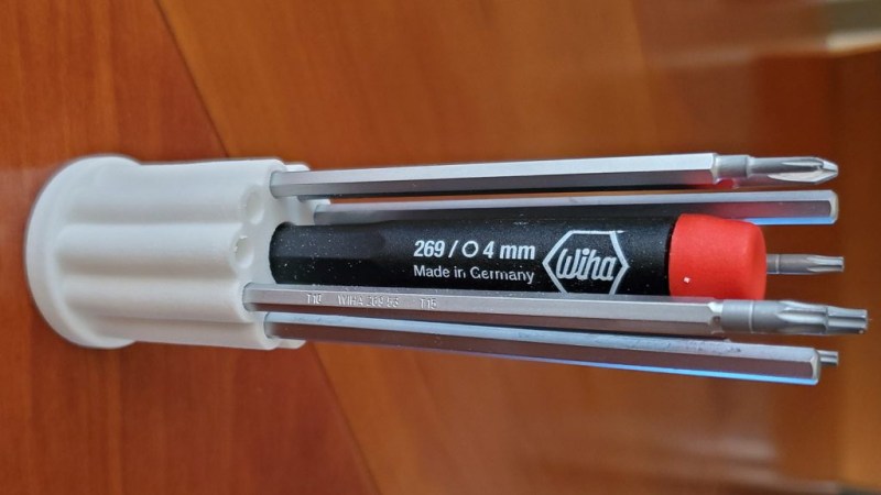
What’s wrong with the above picture? Failure can be an excellent teacher, and [J. Peterson] reminds us all of this when he says to remember to model the environment when designing things in CAD. He contrasts a failure with a success to demonstrate what that means.
The failure was a stand for a screwdriver set, shown above. He modeled up a simple stand to hold a screwdriver handle and the bits in a nice, tight formation. He didn’t model any of parts, he just took some measurements and designed the holder. Everything fit just fine, but it had a major ergonomic problem: you can barely reach the handle because it is fenced in by the surrounding bits! Had he modeled all of the parts during the design phase, and not just the part he was making, this problem would have been immediately obvious during the design phase.
The contrasting success is an adapter he designed to mount an artistic glass marble to a lit display stand. The stand itself as well as the glass marble were modeled in CAD, then the adapter designed afterwards to fit them. With all of the involved objects modeled, he could be certain of how everything fit together and it worked the first time.
Now, to most people with a 3D printer of their own, discovering a part isn’t quite right is not a big (nor even a particularly expensive) problem to have, but that’s not the point. Waste and rework should be avoided if possible. To help do that, it can be good to remember to model the whole environment, not just the thing being made. Add it on to the pile of great design advice we’ve seen for designing things like enclosures and interfaces.


I’m used to call this as “design”
You don’t need to model the items to be held when designing a holder. You just need to measure lenght and use a bit of imagination…
Exactly my thought… and imagination is the most important part of any design, isn’t it?
But even with the best of tools, mistakes like mentioned here aren’t avoided completely. Because well’ some have longer thinner fingers then others, etc. So what’s good enough for some situation is a partial or complete failure for many other.
But the first thing I thought of when I read the text “What’s wrong with the above picture?” was “ha… that’s gonna fall over many times… roll of the desk… and with all these pointy thingies pointing upwards, it’s gonna stick into an eye someday.
Imagination… think what you are going to make and why do you want to make it? I’m pretty sure that this screwdriver set was already in a case when it was purchased?!?! And I’m pretty sure it was a very practical case where you could organize all the bits in a certain way.
To make a long story short, whatever you make it WILL have faults or desires for improvement no tool is going top prevent that. Plan ahead, measure and then measure again then draw it and then double check your measurements.
I would imagine that if you model all of the parts, you can increase the likelihood of the first prototype being workable, especially as things get more complex- more parts involved, constraints on configuration, and so on. This is why, for CNC machines you model the tool, the tool holder, the spindle end,vise, clamps, machine frame, and so on. You need to be able to get the part in and out of the machine, fixture it, and get the tool to it. Same holds for fitted cases to hold tools, product packaging, and so on. You CAN do it without modelling every part, but it will take longer and more revisions, and, in some cases, may lead to expensive failures.
This is certainly true with more complex parts that fit together in non-obvious ways.
The only visualization required here was to imagine the bits extending as far up as the top of the handle. This holder would work find if the bits were shorter.
It is precisely these simple jobs where we are most prone to rush in and fall flat on our faces. Indeed, the time to model a dummy bit and pattern that around in an assembly is trivial – certainly less than even the short time required to reprint a new prototype.
You are right, if we’re dealing with more complex projects and parts, requiring multiple steps in manufacturing, multiple tools and assemblies. But in case of this screwdriver set the only thing one had to do was to place the handle next to the bit to see that bit is much longer than handle…
You say that, but it’s a surprisingly common mistake. The whole point of CAD design is that you can get a good picture of what you’re making and can find and fix problems in advance. By omitting a part of the process and relying on an often very questionable ‘imagination’ you’ll find yourself in trouble sooner rather than later. That’s okay if you just need to print your print once more, but becomes more of an issue when you have things made to order or even find out during final assembly. Shortcuts can be very costly. Model your components and model them with sufficient accuracy.
But isn’t imagination just another word for a mental model?
Not necessarily model the entire parts but at least the interfaces
Anyways best practice is to model parts going into the assembly at LMC or MMC depending on what is the worst case, this serves multiple purposes especially if marketing needs pretty pictures and manufacturing is making work instructions
“Bit of imagination” needs more love. Nicely done.
In my experience as a some-time professional design/CAD engineer[1] it is precisely the times that you decide that all that is needed is a bit of imagination and common sense that you commit the most egregious mistakes.
I think the main thrust of this article, ie the advice to model everything, regardless of whether you think you need to, is valid.
[1] I have been modelling parts in 3D since 1990, but it was only my full-time job for a couple of years around 2000.
I will add “Model your screw heads” to this.
Then you can see if they foul other parts, block rotation etc.
(And have a look at whether any tool can reach them)
Pro CAD software, like Fusion360 (which I use) usually has library of existing parts or could import their models. This is the easiest method to cut gears on CNC mill or laser cutter – grab them from library to get the shape, and then modify their size and design to match yours…
Pro CAD like FreeCAD also supports this:
https://wiki.freecadweb.org/Fasteners_Workbench
Pro cad = fusio360??? Hahahaha
Heh, I worked on a pretty big aluminum-based design last summer, and one of the lessons I learned very quickly after the first attempt is to model your socket set and wrenches. I had measured the diameter of the bolt heads just fine, but it was impossible to fit my ratchet or impact driver over some of the bolt heads because there wasn’t enough clearance for the socket. Very valuable (expensive…) lesson
Don’t worry about it, carmakers haven’t since the 70s, they’ll just design a special offset wrench or dogleg screwdriver and sell it to you for $150 to work on their crap.
And don’t forget thin wall sockets that are guaranteed to fail sooner than later
High pressure steam valves drive me nuts this way. T22 chrome-moly bodies and internals, 4 bolt bonnets, with clearance that demands a special socket to get to the bolt heads, the heads being undersize to begin with (in the US, you have standard and heavy, these heads in question being smaller than standard) The socket ends up being, barely, strong enough to survive the specified torque during reassembly, but not to disassemble a valve that has been in service. Often, the hex cap screws are replaced with socket head caps, which leads to service problems on an 1100PSI steam valve (7.4MPa) operating at 1000F (550C) with superheat. The replacements lose strength.
I have a CNC program for grinding sockets to have clearance to make 1/12 of a turn, and otherwise retain maximum strength.
Just what I thought XD.
Machineries Handbook has nice tables with the standard clearances required for various wrenches. No need to model tools for this, just stick to the standards.
You nailed it. All this stuff is well-known and doesn’t need modeling effort if you can find the specs.
Only American Military Standard gives sizes of Socket sets & Wrenches. Rarely in few other Design Data references, you will find sizes regarding Ergonomics and Operatibility of bolted joints.
Here’s a tip that any MechE will tell you: McMaster-Carr
Not only is it the lifeblood of all small-mid sized engineering firms, it also has CAD models for most items, including every fastener that they offer.
Only really applicable to engineering firms in the USA. (though the CAD models are less location-specific)
As has been mentioned earlier, many packages have (often rather large) libraries of standard fasteners.
I completely agree, I’m a big fan of making the 3D models of my projects as detailed as possible to catch potential problems such as this one early. It forces me to think about every detail and realize that I need some particular size of screw that I may not have in stock, or that there is no way I will be able to fit a screwdriver to tighten that screw, or that a third-party (not 3D-printed) part may actually not fit as well as I initially planned, or…
If this project includes some electronics, it is also useful to import the complete 3D model of it (I do it using Kicad+FreeCAD+StepUp, and I make sure during the layout phase in Kicad that all my components have accurate 3D models), it helps realize that this particular capacitor is too high for the available space in the case, or that the supports around that mounting point mechanically interfere with some components, and so on.
It is usually well worth the time.
I mostly make various kinds of cases/containers for my projects and I’ve picked up the habit of always making rough models of what is going to be inside the case/container already some time ago. It really does help; it’s both easier to keep all the geometry in mind when you have something to fixate on and thus it’s also easier to avoid any major mistakes. A rough model doesn’t even have to take more than a minute to whip up, but it may end up saving you a lot more time in the long run.
Definitely a good habit to train oneself into, IMHO.
Why is that picture sideways?
Because we already had the fail of the week; sideways picture doesn’t count.
The writer forgot to model its environment
Goood one!
Just imagine it’s mounted on a wall.
I made some models to 3D print enclosures for for CNC breakout boards, a stepper motor pulse generator and an Orange Pi Plus 2E. For the OPi I measured and made a block model of the PCB and the components that would fit through the enclosure walls. Perfect fitting first print. When I did that and posted it on Thingiverse, the only other case for the OPi Plus 2E was a crappy clear molded plastic one that was too large so the connectors were in some pretty deep holes.
I designed a 3D printer and modeled every existing part that would go into it. I discovered at different points that some things were impossible to assemble the way I had designed it. I corrected it before I machined the parts and went together reasonably easily.
So assemble the parts you’re designing in design time before actually building it, see if it will go together and plan ahead.
Rule number 1 when designing a print to fit an existing real-world object: model the real world object first. It doesn’t have to be a detailed model, just the rough outline, but any part that’s going to be inside the printed part should be detailed on the surface that contacts the plastic. A bearing can be a cylinder. A piece of t-slot can be a rectangular solid- you don’t have to include the slots or internal anatomy unless the print is going there. Models of screws/bolts/nuts don’t have to have threads.
Does’t need to be a fail. Just print a little male/female insert to raise the handle a few mm above the bits.
Nah, it’s a design feature, it keeps you from working on any project that uses less than four different type of screws.
I’ve learned this lesson many times and now I model everything. I’ve been caught out by things so small as the height of a screw head that I didn’t bother to model.
Also, be sure to take into account shrinkage of 3D printed parts and manufacturing variation – model in some extra space between moving parts.
The beauty of 3D and CAD modelling is that you can fit and test your product before you make anything. This heavily relies on the accuracy of your model, as J. Peterson found out. It’s a classic mistake and taking a shortcut for the shortcut will bite you.
Just use a ruler before you model something this simple. Once you have done a ton of CAD, you realize some things are an absolute waste of time to model.
What? The two minutes for an experienced CAD user to model an extruded cylinder and pattern it in an assembly are killing you?
Do the job right up front and you won’t have waste and rework. In this case a ruler is needed – to measure the parts you want your device to hold.
Yes, that two minutes could be a 10 second measurement with a ruler. When you are paid to do this as a job, time is money.
If you’re sending it to the moon, I completely agree. As a hobby? Or even prototyping? No. Get your build in your hands as quickly as you can. You’ll learn way more about your design and it’s flaws a lot faster by holding it then you ever will in CAD.
Prototypes are great. But you don’t learn anything useful from a prototype with a stupid interference you could have caught be simply modeling the whole assembly. All you’ll do is print the prototype you should have started with in the first place. No, that’s just a waste of plastic — and time.
You need to learn the difference between a prototype and a finished design. You also need to be aware if there are any other outside constraints you are not aware of. For example, did this need to fit in a box? I say that because I have a little tool like that and it does live in a box. You would be bitching just as loud if the box top did not fit on.
All of the unit tests passed.
By the way, if you want to make sure your parts fit together, check out my Fit Testing blocks:
https://saccade.com/blog/2019/12/fit-testing-block/
There is prototype, 3D printed parts and etc. At least you didn’t go all out and make an injection molding die or a die cast die. Sometime a prototype part works fine but a tweek makes it even better. Don’t sweat it.
After you pull the bit out you plan on using, there should be room to grasp the driver. I’m not seeing any major fail here.
The main problem I see, is the whole thing is sideways.