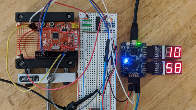
After trying out hardware hacking using an FPGA to interface with target hardware, [Grazfather] was inspired to try using the iCEBreaker (one of the many hobbyist FPGAs to have recently flooded the market) to build a UART-controllable glitcher for the Olimex LPC-P1343.
When the target board boots up, the bootROM reads the flash and determines whether the UART goes to a shell and if the shell can be used to read out the flash. This is meant for developing firmware and debugging it in the bootloader, only flashing a version when the firmware is production-ready. The vulnerability is that only a specific value read from address 0x2FC and the state of a few pins can lock the bootloader in the expected way, and any other value at the address causes the bootROM to consider the device unlocked. Essentially, the mechanism is the opposite of how a lock ought to work.
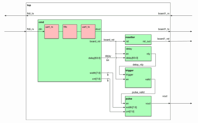
The goal is to get the CPU to misread the flash at the precise moment it is meant to be reading the specific value, then jumping to the bootloader in the unlocked state. The FPGA can be used as a tool between the host machine and target board, communicating via UART. The FGPA can support configuring the delay between resetting the target board and pulsing a ‘glitch voltage’, as well as resetting the target board and activating the glitch. The primary reasons for using the FPGA over a different microcontroller are that the FPGA allows for precise timing (83.3ns precision) and removes worries about jitters (a Raspberry Pi might have side effects from OS scheduling and other processes and microcontrollers might have interrupts messing up the timing).
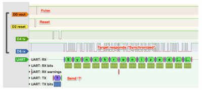
To simulate the various modules, [Grazfather] used Icarus Verilog as well as GTKWave to observe the waveforms generated. A separate logic analyzer observes the effects on real hardware.
With enough time, it is possible to brute force any combination of delay and width until you get a dump of the flash you’re not meant to read. You can check out how the width of the pulse gets wider until the max, when the delay is incremented and the width values are tried again.


>FPGA allows for precise timing (83.3ns precision)
That’s a very odd way of saying resolution.
83.3ns is only 12MHz; that’s just sad.
He compares it to using a Raspberry Pi with an OS and timing in software (really?!?), and an Arduino where interrupts would mess up the timing.
Only a unknowledgeable beginner would try to do such timing from a software loop; using a hardware timer (PWM periferal) is the obvious way to do this. A STM32F407 can run it’s PWM periferals from 168MHz, which is ~6ns resolution, and some motorcontrol-specific parts from Texas Instruments can get PWM resolution in the tens-of-picoseconds range.
Even using a second board with the same microcontroller (LPC-P1343) would give 72MHz system clock, so 13.8ns resolution.
Of course all of this only works because the controller apparently doesn’t have a proper on-board brown-out detection and reset circuit, which I find highly surprising.
I’d think another way to produce a similar glitch would be to generate the clock for the CPU with a FPGA or faster CPU, and generate a clock pulse with a shorter interval at just the right time, thereby violating the flash timing specifications. This assumes the CPU is running from an external clock while the code is question is being executed.