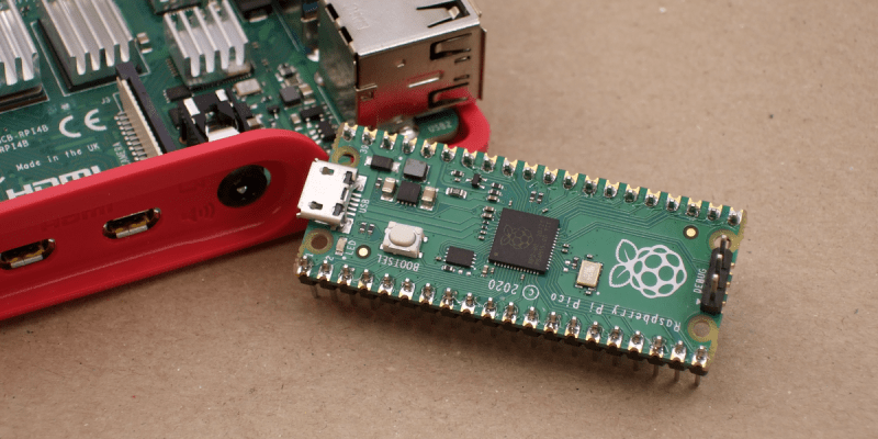
Raspberry Pi was synonymous with single-board Linux computers. No longer. The $4 Raspberry Pi Pico board is their attempt to break into the crowded microcontroller module market.
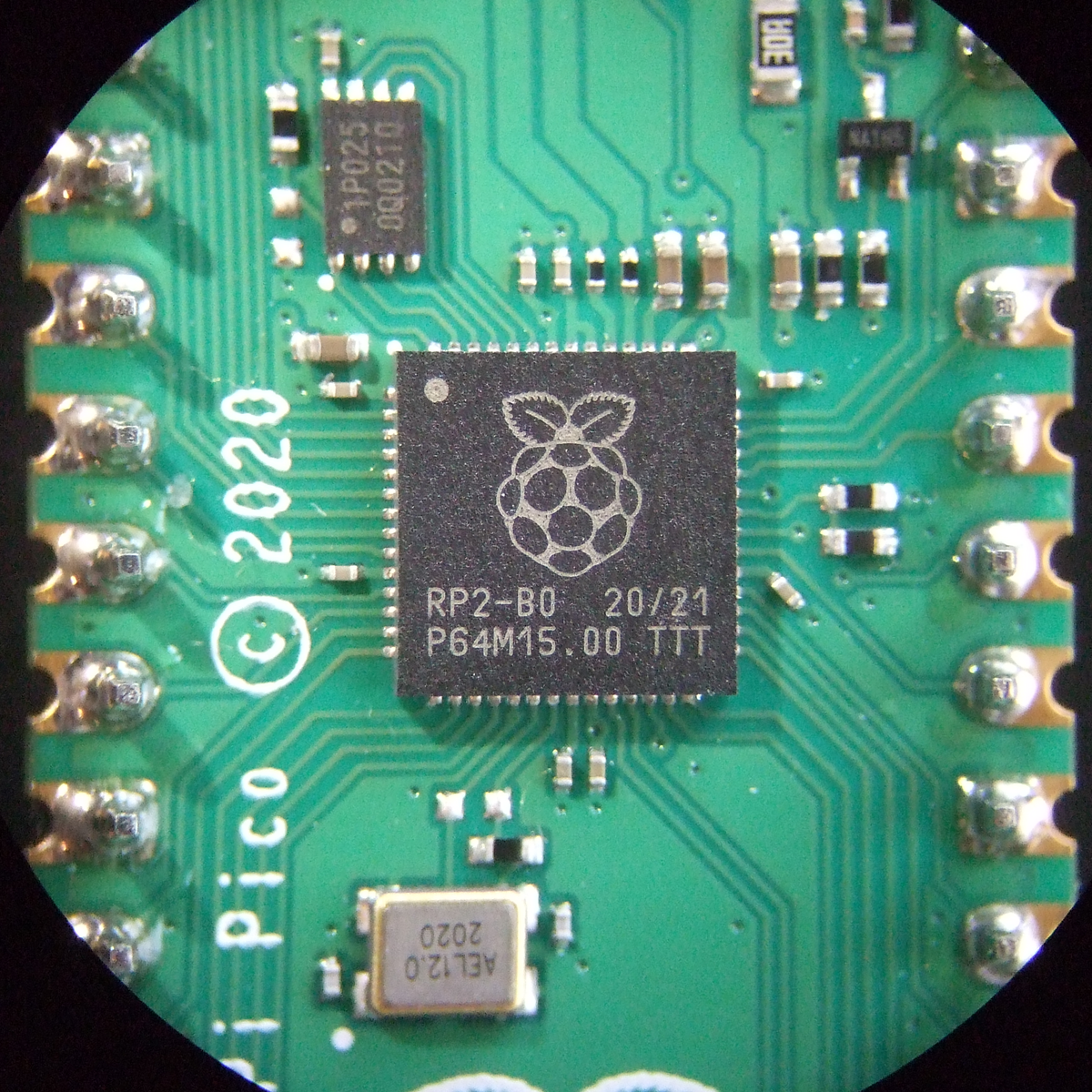
The microcontroller in question, the RP2040, is also Raspberry Pi’s first foray into custom silicon, and it’s got a dual-core Cortex M0+ with luxurious amounts of SRAM and some very interesting custom I/O peripheral hardware that will likely mean that you never have to bit-bang again. But a bare microcontroller is no fun without a dev board, and the Raspberry Pi Pico adds 2 MB of flash, USB connectivity, and nice power management.
As with the Raspberry Pi Linux machines, the emphasis is on getting you up and running quickly, and there is copious documentation: from “Getting Started” type guides for both the C/C++ and MicroPython SDKs with code examples, to serious datasheets for the Pico and the RP2040 itself, to hardware design notes and KiCAD breakout boards, and even the contents of the on-board Boot ROM. The Pico seems designed to make a friendly introduction to microcontrollers using MicroPython, but there’s enough guidance available for you to go as deep down the rabbit hole as you’d like.
Our quick take: the RP2040 is a very well thought-out microcontroller, with myriad nice design touches throughout, enough power to get most jobs done, and an innovative and very hacker-friendly software-defined hardware I/O peripheral. It’s backed by good documentation and many working examples, and at the end of the day it runs a pair of familiar ARM MO+ CPU cores. If this hits the shelves at the proposed $4 price, we can see it becoming the go-to board for many projects that don’t require wireless connectivity.
But you want more detail, right? Read on.
The Specs and the Luxuries
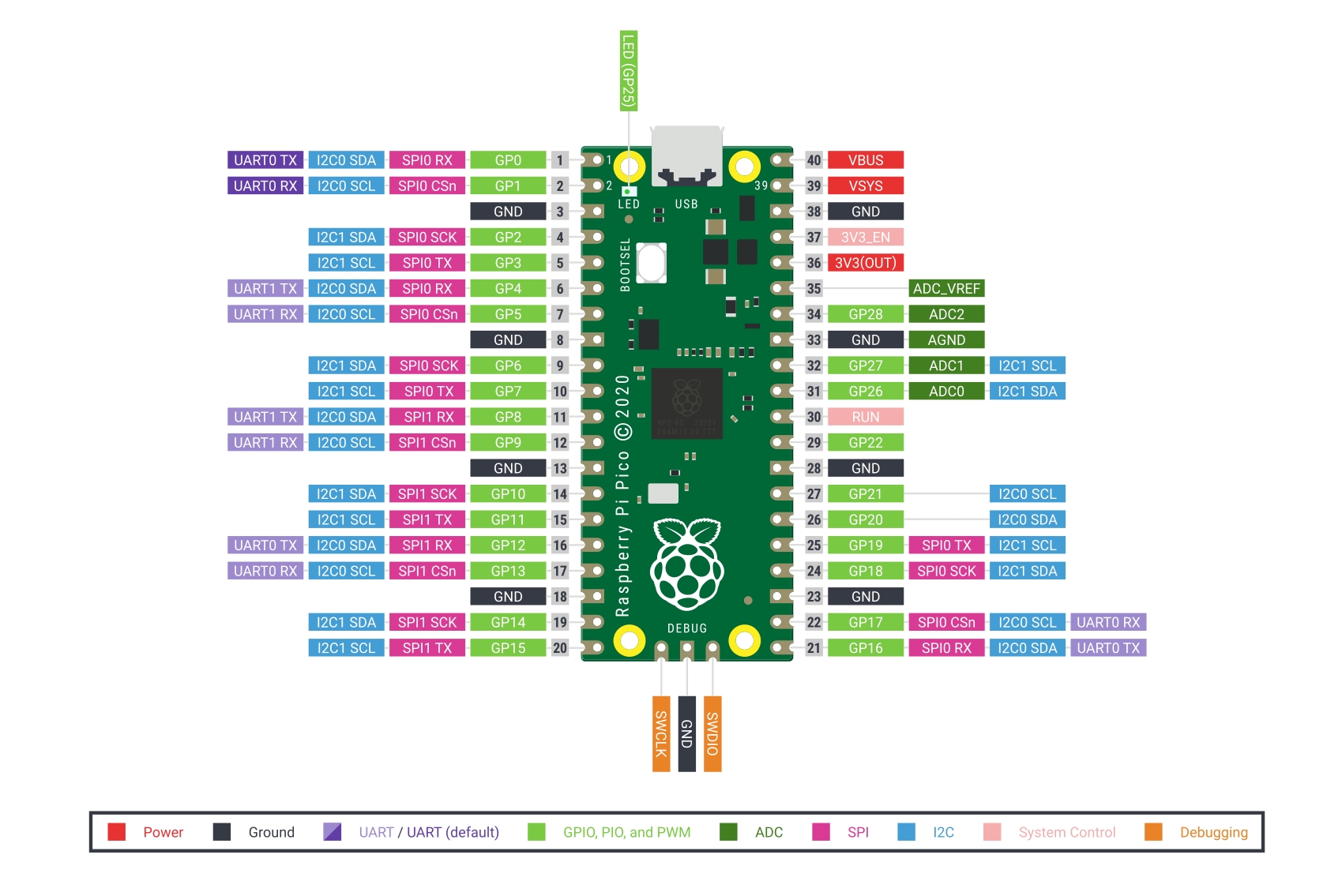
In many ways, the Pico is a well-appointed “normal” microcontroller board. It has 26 3.3 V GPIOs, a standard ARM Serial Wire Debug (SWD) port, USB host or device capabilities, two UARTs, two I2Cs, two SPIs, and 16 PWM channels in eight groups. (The PWM unit can also measure incoming PWM signals, both their frequency and duty cycle.) The Pico has a 12-bit ADC, although it’s connected to only four three pins, so you’ve got to be a little careful there. (Ed note: the RP2040 has four ADCs, but the fourth isn’t available on the Pico.)
The twin ARM M0+ cores run off of PLLs, and are specced up to 133 MHz, which is pretty fast. There are separate clock dividers for nearly every peripheral, and they can be turned on and off individually for power savings, as with most other ARM microcontrollers. It runs full-out at around 100 mA @ 5 V, and has full-memory-retention sleep modes under 1 mA.
As the ESP8266 and ESP32 modules do, it uses external flash ROM to store programs, and can run code directly from the flash as if it were internal memory. The Pico board comes with a decent 2 MB QSPI flash chip, but if you’re handy with a soldering iron, you can fit up to 16 MB. It has 264 kB of SRAM, which is certainly comfy. The RAM is divided up internally into four striped 64 kB banks for fast parallel access, but they’re also accessible singly if you’d like. Two additional 4 kB banks are non-striped and suggest using themselves as per-core stack memory, but nothing forces you to use them that way either.
There are numerous minor hardware-level conveniences. All of the configuration registers are 32 bits wide, and so you might not want to have to specify all of them, or maybe you want to avoid the read-modify-write dance. Like many of the STM32 chips, there is a special memory map that lets you set, clear, or XOR any bit in any of the config registers in a single atomic command. There are also 30 GPIOs, so they all fit inside a single 32-bit register — none of this Port B, Pin 7 stuff. This also means that you can read or write them all at once, while setting individual pins is easy through the above atomic access.
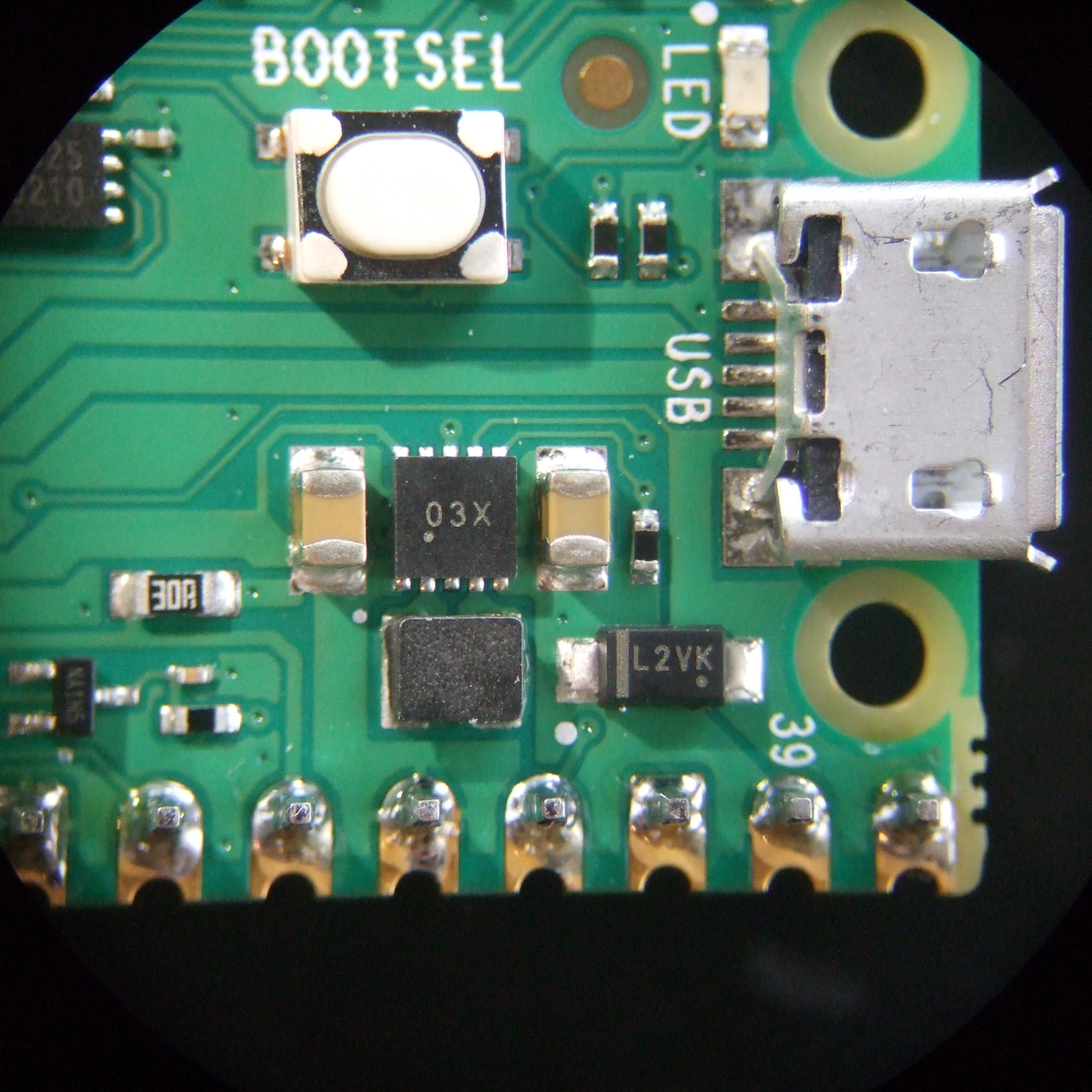 An internal mask ROM contains the UF2 bootloader, which means that you can always get the chip back under control. When you plug the Pico in holding down the BOOTSEL button, it shows up as a USB mass storage device, and you can just copy your code across, with no programmer, and Raspberry even provides an all-zeros file that you can copy across to completely clean-slate the machine. If you copy the Pico’s MicroPython binary across, however, you’ll never need the bootloader again. The mask ROM also contains some fast routines that support integer and floating point math, and all of the contents are open source as mentioned above.
The power regulation onboard is a boost-buck configuration that takes an input from 1.8 V to 5 V. This is a good range for lithium batteries, for instance, which can be a hassle because they run both above and below the IC’s 3.3 V, so it’s nice to have a boost-buck regulator to squeeze out the last few milliamp-hours. Or you could run your project on two AAs. That’s nice.
So the Pico/RP2040 is a competent modern dev board with some thoughtful touches. But it gets better.
The PIO: Never Bitbang Again
The real standout peripheral on the RP2040 and the Pico is the Programmable I/O (PIO) hardware, which allows you to define your own digital communication peripheral. There are two of these PIO units, and each one has four programmable state machines that run sequential programs written in a special PIO assembly language. Each of the state machines has its own clock divider, register memory, IRQ flags, DMA interface, and GPIO mapping. These allow essentially arbitrary cycle-accurate I/O, doing the heavy lifting so that the CPU doesn’t have to.
 If you want to program another UART, for instance, it’s trivial. But so is Manchester-encoded UART, or a grey code encoder/decoder, or even fancier tricks. One of the example applications is a DPI video example, with one state machine handling the scanline timing and pixel clock, while another pushes out the pixel data and run-length encodes it. These are the sort of simple-but-fast duties that can bog down a CPU, leading to timing glitches, so dedicated hardware is the right solution.
The PIOs are meant to have a lot of the flexibility of a CPLD or FPGA, but be easier to program. Each state machine can only take a “program” that is 32 instructions long, but the “pioasm” language is very dense. For instance, the command to set pin states also has an argument that says how long to wait after the pins are set, and additional “side-set” pins can be twiddled in the same instruction. So with one instruction you can raise a clock line, set up your data, and hold this state for a defined time. A basic SPI master TX implementation is two lines.
Or take the example of the WS2812 LED protocol. To send a logical 1, you hold the self-clocked data line high for a long period and low for a short period. To send a logical 0, the data line is held high for a short period and low for a long one. Creating the routines to do this with reasonable speed in the CPU, without glitches, required a non-trivial shedding of hacker tears. With the PIO peripheral, writing a routine to shift out these bits with absolute cycle accuracy is simple, and once that’s done your code can simply write RGB values to the PIO and the rest is taken care of.
To run PIO code from C, the assembler is called at compile time, the program is turned into machine language and stored as a matrix in a header file, and then this can be written to the PIO device from within main() to initialize it. In Python, it’s even easier — the @asm_pio decorator turns a function into PIO code. You just have to write the “Python” function using the nine PIO assembly instructions and then hook it up to GPIO pins. After that, you can call it from your code as if it were a normal peripheral.
Having played around with it only a little bit, the PIO is the coolest feature of the Pico/RP2040. It’s just a little bit of cycle-correct programmable logic, but most of the time, that’s all you need. And if you don’t feel like learning a new assembly language — although it’s only nine instructions — there are a heaping handful of examples already, and surely folks will develop more once the boards hit the streets.
IDEs and SDKs: C and MicroPython
The Raspberry Pi single-board computers (SBCs), when combined with their documentation and examples, usually manage a nice blend of being simple enough for the newbie while at the same time not hiding too much. The result is that, rather than having the underlying system’s Linuxiness abstracted away, you get introduced to it in a friendly way. That seems to be what the Raspberries are aiming at with the Pico — an introduction to microcontrollers that’s made friendly through documentation and MicroPython’s ease of use, but that’s also not pulling any punches when you turn to look at the C/C++ code.
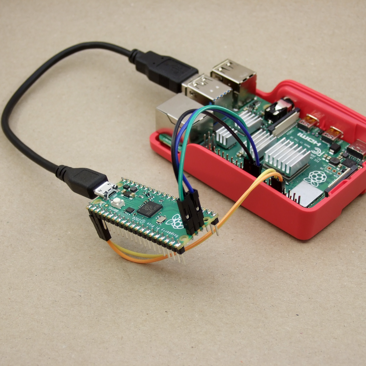
And having a Raspberry Pi SBC on hand makes a lot of the most hardcore microcontrollering simpler. For instance, if you want to do debugging on-chip, you’ll need to connect over the SWD interface, and for that you usually need a programmer. But of course, you can also bit-bang a SWD controller with the GPIOs of a Raspberry Pi SBC, but you’ll have to configure OpenOCD just right to do so.
If that all sounded like gibberish, don’t worry — all of this is taken care of by a simple pico_setup.sh script. It not only installs all of the compilation and debugging environment, it also (optionally) pulls down VScode for you. Nice.
And you will want to program it over the SWD eventually. The cycle of unplugging USB, holding down a button, and re-plugging USB gets old real fast.
If you’re a command-line junkie, the C SDK’s build system is based on CMake and runs just fine from the command line if you’ve already got the ARM toolchain installed. And as with all SDKs, there’s a certain amount of boilerplate necessary to start up a new coding session. This is taken care of by the pico project generator, so you don’t have to.
In the “Getting started” guides, you’ll find instructions for setting up your environment on a Raspberry Pi SBC, Windows, Mac, or desktop Linux machine. If you prefer Eclipse as an IDE, there are integration instructions as well.
Two Cores: Here be Dragons
If there’s one area that strikes me as not yet fully developed, it’s the dual-core aspect of the system. Right now, if you write either C or Python code, it’s running on Core 0, while Core 1 is simply sitting idle. Both the C and Python SDK documentation tell you how to start up a thread on the other core, and there’s example code available as well, but the instructions are sparse. In C, there’s a pico/multicore.h and even mutex, semaphore, and queue libs for you to include, but the documentation warns that most of the stdlib functions aren’t thread-safe. In Python you import _thread and call the start_new_thread() method, but I don’t know how much fine-grained control you have.
If all of the above sounds scary, well, it is a little. The truth about coding for multiprocessor systems is that it opens up new ways for things to go wrong, as one CPU changes values out from under the other, or they both try to write out to the UART at the same time. We wrote the Raspberries and asked if they were planning to port over an RTOS, which provides a little more structure to the problem, and they replied that that was actually first on their plate after they get through the release. So unless you know what you’re doing, you might not get the full benefit of the dual-core chip just yet. But we’re honestly looking forward to an RTOS getting the Raspberry Pi documentation-and-tutorial treatment when it happens.
Deep Thoughts
It’s not every day that you see a new player enter the microcontroller market, let alone one with the hacker-friendly qualifications of Raspberry Pi. For that alone, this board is notable. But the feature set is also solid, there are many creature comforts in both the silicon and the support, and it brings one truly new capability to the table in the form of the PIO units. Add to all this a price tag of $4, and you can imagine it becoming folks’ go-to board — for those times when you don’t need wireless connectivity.
 Indeed, the only real competitor for this board in terms of price/performance ratio are the various ESP32 boards. But they’re also very different animals — one offers fewer GPIOs but has extensive wireless features, and the other has more (and more flexible) GPIO, device and host USB, but no radio. Power consumption while running full-out, with wireless turned off, is a slight advantage for the ESP32, but the sleep modes of the Pico are slightly thriftier. Both SDKs get the job done in C, and both run MicroPython. ESP32’s dual cores run FreeRTOS, but we imagine it won’t be very long before that playing field is levelled. So basically it’s down to WiFi vs USB.
Of course, for slightly less money, one can pick up one of the STM32-based “Black Pill” boards, with yet another set of pros and cons. Choices, choices!
With the Pico, Raspberry Pi is entering a crowded field. They’ve got the name recognition, a cool hardware trick, a great value proposition, and a track record of solid documentation. If I were coding up a GPIO-heavy application without the need for wireless, the Pico would be a solid choice, especially if I could make use of the extra core.
I’ll leave you with a teaser: On page 9 of the RP2040 datasheet, they lay out what “2040” stands for: two cores, type M0+, more than 256 kB RAM, and zero kB flash. Does that mean we’ll eventually see models with more RAM, onboard flash, or different ARM cores? RP2050? RP2048? Speculate wildly in the comments.


Will you actually be able to buy more than one of them at that price, or is this just doomed to be another repeat of the Pi Zero fiasco?
You can buy 100,000 of them at that price if you want!
As long as there’s hardware meant to be sold as cheaply as possible, there will always be scalpers and hoarders.
This is not why Pi Zero supplies were (and still are) supply constrained. It’s because of their rather eccentric approach to manufacturing.
Zeroes are supply constrained? I’ve never not seen them available at Microcenter when I rummage around the Hobby section.
When they were first released, the scalpers were everywhere!
Totally spitballing here, but the price is very fair, but not totally out of whack either.
The board has the chip, power, flash, a crystal, an LED, and a button: seven parts that aren’t caps or resistors. B/c the USB is handled on-chip, there’s no USB-UART chip, and all-in-all, it’s a much smaller BOM than on an ESP32 board, for instance, and they run $4-$5.
I’m glad they splashed out on a nice boost-buck power section, but other than that, there’s only the flash chip that separates this from the $2 blue pill boards.
I haven’t seen pricing on the RP2040 bare chips yet. Anyone?
I’d guess their margin is very tight, but I don’t think they’re losing money.
The Pi Foundation is probably fine (They mention debugging one with another one, so clearly they plan to support you buying at least two), but scalpers could still trash the whole thing to thee point where we’re paying $12 for a full kit with crappy laser cut cases we don’t even want.
plus an arm and a leg for shipping and you can only order 1 in each order.
Hey Statler and Waldorf, is that really you? ;-)
You can connect the debug with a Raspberry Pi Linux computer, no need to use another RPi pico.
And it is two M0+ cores, with a special small CPU for IO, so you don’t need to bit bang other protocols, like for those popular leds and other easy protocol. They can also produce interrupts to the main CPU:s
Yes, it is a nice and well though through for what it is designed for. Both the chip and the break out board it sits on.
The RP2040 chips are 40nm, and 2mm^2 in size – they have a lot of room to manoeuvre in bare chip pricing as they might get 10,000 per wafer (assuming 8″ wafer).
There are several third party boards already designed, and listed on the RPi website, including an Arduino with Wifi+BT.
You can get a free Pico with a magazine as well this month. I think they’ve made enough (in Japan, this time, not UK).
Magazine name??
Wait.. nevermind, I found all the info and realized what you’re saying a bit better. The Pico’s are made in japan, but the magazine is hackspace magazine, which is only affordable in the uk. £90 for a subscription which starts at issue 40, when the pico comes with issue 39 is also quite tricky when they suggest you can get the pico with a subscription on the raspberry pi blog. Super disappoint.
John, there’s a free Pico on the front of Issue 39 of Hackspace, but their subscriber offer is also now a free Pico (it used to be a Pi Zero). So if you were able to start your subscription at issue 39 you’d get two boards, one freebie on 39’s cover, and one as part of your subscription. 39 seems to be out of stock now, unfortunately.
Shoe, thanks for the update, but still £90 is a lot for a pico and some magazines. I’ll try to find a single issue of 39.
Dang, I think Hackspace is available at the big Walmarts that have overpriced Pi and related robot and STEM kits in the electronics section. But I’m not near enough any of them. thanks for the headsup Shoe. We’re under heightened covid restrictions here though atm so I can’t really troll a bunch of stores looking for it. Though I’ll certainly check for it at stores I need to go to anyway over the next month.
ESP32 boards are $4-5 retail. If you buy 1,000 of them they are $2. RP2040 is still $4 if you buy 1,000.
Damn Elliot, you got a phrasebook that’s called “Hello Fellow Kids” or what?
I was originally referring to the “one per household” policy on the OG Pi Zero per the RPi foundation that is still in place, not the supply issues at launch.
The supply issues were fixed long ago, but I still can’t buy more than one from official distribution channels in the same order.
Pimoroni have a “3 per customer” limit for Pico sales in the UK.
Limits will be relaxed for Pico once the sales pipeline is filled.
Adafruit has them bouncing in and out of stock. Limit 3/order. IDK if you can submit multiple orders/day.
The basic Zero $5 price is a subsidised educational price. You can buy multiple ZeroW or ZeroWH but they are more expensive. You can also buy multiple basic Zero’s but you will pay more as they won’t have the educational subsidy.
You can’t. ZeroW are similarly restricted. ZeroWH are supposed to be unrestricted but are often restricted just the same. Go and look on e.g. Adafruit.
The thing about scalpers is the nearest microcenter sells pi zero W for $10 and cheapest Amazon is $18.48 so scalpers with their 84.8% profit margin amirite?
However, when you actually run the numbers, the nearest microcenter is 100 miles away so figure at least 50 cents per mile, plus sales tax plus highway tolls and I can buy one pi zero and be home in three hours for maybe $125 or so. The scalper only wants $20 and 60 seconds on amazon.
On the other hand, a USPS flat rate priority mail box is $8.30. That means the “scalper” on amazon is pocketing a staggering eighteen cents of corrupt profit for the privilege of printing out a shipping label and tossing a pi in a box and tossing it in a mailbox.
So if I participate in the scam economy and buy from the scalper I save myself three hours of driving and about a hundred bucks of wear and tear on the car which is nothing to laugh at. Also you can’t freely swap between billable hours and hobby hours but if you could then driving out to get the pi is going to cost me a couple hundred bucks lost in billable hours.
Now if some guy living in Chicago is “scalping” 100 pi at a time every day as a side hustle, I can respect that and it multiplies out to paying for the guys lunch every day, and I’m good with that. It saves me a lot of money and is very convenient.
And you can get a RPi pico (and could get a RPi zero W) for about $90 AND a year subscription for a magazine, sent home to you.
“I couldn’t get one of a massively in demand item instantly, so I’m gonna be salty about it forever” Hope that’s working out for you.
Here in Australia they literally have 2500 units ready to go, and we’re the arse end of the world.
More importantly, the product’s Australia tax is quite reasonable.
No, more like “The Raspberry Pi Foundation’s official policy is that you are only supposed to be able to purchase one Pi Zero, and all official distributors limit to one per household”
I’d appreciate if someone could provide a link to a supplier in the US where one can purchase more than one Pi Zero (non-W) from for close to $5/each? Because the fact that I can’t buy them for anywhere close to $5 due to having to have them shipped individually is honestly is what has kept me ftom building projects using them so far.
The PI zero slower than death anyway. I bought one a while back because it sounded cool, but dozens of project later I’ve yet to find one that’s not better suited to a regular pi or a microcontroller.
I guess the low price is cool, but if I’m going to spend 10 hours getting something working I can afford to spend 10 dollars on the MCU instead of 5.
I saw many stories of people going to Micro Centre and getting a bunch at a time.
When I go to Micro Center, I can buy (1) Pi 4, 1 Pi Zero, 1 Pi ZeroW, and maybe a Pi 3, (per day) if they are in stock.
What can you build with it? I’m totally new and have no idea what toys I can make.
Anything you can make with a Pi, only it’ll run slower and require more effort on your part.
You can go thru the motions, challenges, and thrills of setting up a very small cheap and portable compute cluster, very educational.
The various bus options are easy to interface to. Buy some stereotypical weather sensors like the $3 BME280. Lets say ten of each. Then solder them together and scatter thru the house and do some data science magic to graph how humidity flows thru the house when you boil up some pasta in the kitchen or how you can actually measure the speed of the furnace air in the ducts as the house slowly warms when the furnace is on etc etc etc.
Its hilarious to stick a $5 magnetometer or $2 light sensor on a pi and try to do presence detection across ten or so pi scattered thru the house.
You can learn a lot about AWS and IOT by turning them into IOT devices that uplink to amazon and do all your data analysis in the cloud. You certainly don’t have to, to handle five temperature sensors, LOL. But the whole point is learning to play with AWS and IOT tools. I mean its not really a pi project at that point its a project that uses pi.
Even if you only buy two or three you can learn a lot about I2C by making them talk to each other over I2C. Or for the more ambitious try to reimplement IRDA infrared networking.
Pi make halfway decent digital picture frames or magic mirror drivers. The only thing better than one digital picture frame is maybe four synchronized-to-each-other frames. Also e-ink status displays are kinda cool.
You can have a lot of fun with about five or so pi. Alone with bare hardware you can’t do much more than make a cluster but attach almost any sensor and multiple devices will be fun.
Anything you can do with any other cheaper micro-controller (AVR, STM32F1 and thousands more)
This arrives a little late to the game.
yet if I want to buy a Pi zero, I can still only buy one at a time, and then pay shipping on top of it. so I am paying 25 for each and everyone I use.
I am in Melbourne, so this is a 100% attack on the way it works here.
Sparkfun: “We have an order limit of 100 per customer on this product.”
Price: $4.
Sparkfum on Thu., 21-Jan-2020, 21:35 EST: “BACKORDER. We have 1328 incoming. We do not have an estimated date yet. Incoming stock values are estimates, and subject to change without warning. Note: We have an order limit of 100 per customer on this product.”
Yeah, typical Raspberry Pi unobtainium syndrome.
Adafruit too!
“And we have plenty, so don’t worry about it. We’re not gonna run out in like…two minutes. There’s a lot of supply […] we got many thousands of these so I’m not concerned about it” – Adafruit livestream @ ~02:00 CST
“IN STOCK” – Adafruit twitter 13:49 CST
“OUT OF STOCK. Please enter email to be notified when this product is back in stock” – Adafruit website at 20:48 CST
I placed my order on Sparkfun within 15 minutes of this article getting posted, so hopefully I’m at least at the front of the line, but it still hasn’t shipped, so who knows!
Just bought 3 of them on sparkfun with no problems. The total was like 20 bucks with shipping and tax.
i just purchased 5 to play with and give to friends. So yup no restrictions that i could see.
As far as I can tell it’s impossible to actually buy it for $4
133mhz dual core M0+ with 265k of sram
That’s rather impressive and quite compeditive even at twice the cost
I have been relying on bluepill clones for my goto cheap ARM boards
It’s no M4F but it would still be very very useful
Nice to have two cores, but since they are M0+: no I-cache.
It basically means that one can run from flash, the other from ram. If both run from flash it will basically means that it will be faster to run one core.
There is a 16K (separate from the SRAM) two way cache for the XIP flash, so many programs will be fine out of the box. You can move any C function into RAM via a decorator macro, and of course the floating point routines are in ROM, so no contention there. Also the SRAM is striped to minimize contention.
They could have done it that way but it seems like they did not. I welcome corrections on this comment…
The spec mentions a 4:10 crossbar. (see page 14, the pic helps) The 4 bus masters (both cpu’s and dma) can all access the 10 slaves simultaneously (not the same slave)
the memory is broken into 5 banks so you should be able to run one core from one bank and another from another bank without slowing down. matrix has 2GB/sec BW.
Now the rom looks like it is single slave port so maybe some occasional arbitration there.
Same if the cores are accessing the same bank for some shared code or data..
I would probably load from the flash into sram and go. Maybe it allows one core to run xip from the flash and the other from sram… The spi is QSPI , not sure the speed they are running at for slowdown.. I need to read more details and see if there are app notes. If you have a big program that’s a whole different thing, dma in/out chunks etc..
Hoping there is an m33 version with I$/D$ in the works.
Note also the M0+ is executing mostly 16 bit instructions, but does 32 bit fetches. There is a lot less contention than you would expect and you can get two cores plus DMA going flat out without much trouble.
The two smaller memories contain the two stacks by default, which is a decent fraction of your load/store bandwidth pointed at memories that are by convention core private (although this isn’t enforced in hardware, you can do whatever you want with your RAM). You can also stash some core-private hot code in those memories if you need guaranteed access, and there are macros to do this in the SDK.
Some thought went into this!
> there is a special memory map that lets you set, clear, or XOR any bit in any of the config registers in a single atomic command
That isn’t uncommon on microcontroller ARM chips.
Which was pretty much stated in the other half of the sentence you conveniently left off. Sure, it’s not limited to STM32, but it’s not like Elliot was claiming it’s a novel feature either.
Is it a standard ARM feature? I haven’t dug really deep into any of the ARMs outside of ST’s offering.
ARM provides bitbanding as an option for most (all?) of the Cortex-M cores.
Interestingly it looks like it’s definitely “most” – M0 and M7 don’t have it, and the RP2040 has what must be a custom implementation specifically for the peripheral register regions.
Note bitbanding is entirely useless on a system with two cores. The access might be atomic from the software point of view, but it’s still a read-modify-write on the _bus_, so the accesses still race.
Doesn’t a mutex implemented in hardware let you use bitbanding on a multicore chip.
All you need is an atomic instruction to test a bit and leave it set after testing. Then each core can test that bit and use it as a gate before starting a read-modify-write sequence. I can’t believe any modern multi-core chip would lack that instruction.
Oops, last comment was hasty, bitbanding is implemented as read-modify-write on the bus but is safe if your vendor bus fabric implements bus locking correctly (which is part of the required bus standard)
Anyway M0+ does not have bit banding natively, though some vendors choose to hack it on with a wrapper around the processor.
On RP2040 all the registers support set/clear/xor of the entire register, and this is a native function of the actual register blocks. It’s a bit more general than bitbanding, makes it easier to update multiple fields at once.
@pelrun said: “ARM provides bitbanding as an option for most (all?) of the Cortex-M cores.”
@Luke Wren said: “Note bitbanding is entirely useless on a system with two cores. The access might be atomic from the software point of view, but it’s still a read-modify-write on the _bus_, so the accesses still race.”
In the ARM Cortex M3/M4, bit-banding read or write operations are not Read-Modify-Write (RMW). Indeed the whole purpose of bit-banding is to avoid using multiple instruction cycles to read or write from/to a register bit, like needed with RMW operations. The problem solved by bit-banding is that with RMW, something might change between one of the instructions (e.g. pin-change interrupt), this can potentially cause a race condition.
A bit-banding read or write operation is atomic and takes place in a single instruction cycle. All M3/M4 cores on die are clock coherent, so during a bit-banding operation nothing can change.
Regardless, I believe bit-banding is only available on the ARM Cortex M3/M4 chips. So unless the ARM Cortex M0 IP being used on Rapberry Pi’s RP2040 chip has bit-banding added to it (not likely), then there must be another mechanism in-place to prevent race conditions from occurring between the two M0 cores. That would be a good question for the RP2040 designers. Maybe there’s a commutator between the two cores, or some mutex/semaphore magic might be happening.
Here are a couple of bit-banding links:
1. Bit-banding – An Elegant Approach to Setting & Clearing Bits
https://spin.atomicobject.com/2013/02/08/bit-banding/
2. Cortex-M3 Embedded Software Development – AppsNote179, Sec.-2.5 Bit-Banding
http://infocenter.arm.com/help/index.jsp?topic=/com.arm.doc.dai0179b/CHDJHIDF.html
Bitbanding only allows you access to a single bit at a time. This allows you access to 32bits at a time *and* allows you to and/or/xor any of them; with bitbanding you can only set or clear in a single instruction and you will need to do the address calculation for each bit to be modified somehow.
there is an alliance
Arduino: https://blog.arduino.cc/2021/01/20/welcome-raspberry-pi-to-the-world-of-microcontrollers/
Adafruit: https://www.adafruit.com/feather2040
and Sparkfun:https://www.sparkfun.com/news/3707
Dang, the Maker-Industrial Complex is real! ;-)
Pimoroni: https://blog.pimoroni.com/pico/?goal=0_3772e11665-8df26a1429-104669445&mc_cid=8df26a1429&mc_eid=389e0d90ab
This looked nice but not really interesting to add to my giant pile of microcontroller boards until I saw that PIO feature… dang.
More skulls for the skull throne!
No, no. PIO experimentation from the MicroPython REPL!
I think this’ll be really interesting for a whole bunch of really strange use cases. Stoked.
Realtime hardware decoding of cheap digital calipers for use as position encoders on servo-based CNC machines comes to mind.
no need for PIO, calipers are only 10Hz output, 50Hz for the ones that support fast mode, hardly a realtime issue.
Yeah. I went from “meh another microcontroller” to “I WANT ONE NOW”.
Most people just drive Canon EF lenses with a normal SPI controller, ignoring the possibility the lens might try to insert busy states. But the real Canon EF protocol is a variant of SPI where the lens can hold the clock line low to stop data transfer. PIO would be perfect for this.
It sound a bit like I2C clock stretching.
Micro-USB? Really? USB-C would have been a much better option :-(
Good thing nobody is forcing you to buy it! :-)
Someone must, otherwise there wouldn’t be a market for scalpers*, and hence complaints.
*In general. Not this board specifically.
Adafruit have a RP2040 based “feather” board that uses an USB-C connector
I hate USB-C, the cables are either fully featured, and become too thick and stiff, or the cables are not fully featured, and don’t work when you expect them to. Meanwhile, I can tie a knot with my USB micro cables and it’ll still work.
except there are power only and data also style micro-USB cables around. The former are abundant when coupled with a power supply with USB-A socket.
I would have preferred USB-C too but it isn’t that much of a deal breaker to me. I got plenty of both cables lying around.
Oh my. This is going to take a minute or two to digest. Thanks, Elliot, I didn’t have enough to think about already!
“The Pico has a 12-bit ADC, although it’s connected to only four pins, so you’ve got to be a little careful there.”
Eliot, care to show where the 4th ADC input is on the Pico?
The fourth pin goes to an internal temperature sensor.
Depending on phrasing… There are 4 ADC-capable pins on RP2040, and all are used on Pico, but only 3 are broken out on the edge pins. The fourth RP2040 ADC pin can be used to measure the VSYS voltage via a resistive divider.
There is a fifth ADC input on RP2040 which connects to the internal temperature sensor.
The fourth external input also goes to a testpoint on the back, and pico can be surface mount soldered as a module, which lets you break out these test points onto your board. That lets you use the fourth external input.
Dual-core seems like a crazy idea, it only invites endless complexity and nightmares… I’d rather have a little faster M4 core! It also sounds like they have not paid much attention to power consumption if it burns more than an esp32… On the price front, doesn’t an esp32-s2 pack more performance, a lower price, usb, and wifi, and bluetooth?
ESP32-S2 doesn’t do Bluetooth and doesn’t have anything comparable to PIO.
The ESP32-S2 does have the “ultra low power” co-processor, which on that device you can run in RISC-V mode. Taking a quick look, it can run while the main CPU is running, not just only while in sleep mode.
The s2 doesn’t have bluetooth and is single core.
I think you are wrong on the multiple cores (though I agree I’ve been writing for multiple cores for quite a few decades) – it is really really really useful to have. And it isn’t that hard to do safely – ie thread safe queues are your best friend, as are thread safe events :-).
The power comparison might not be totally fair. I should really do that right. The numbers from the Pico are with it running basically flat out on both cores: doing video and I2S audio. I fear I might have been comparing a max value to an average value in my mind.
The ESP32s are actually pretty good with power, considering clock speed and peripheral load, once you turn the radio off. With the radio on, you can kiss your batteries goodbye. :)
Neither of them have very good sleep power draws, in my book. When an AVR sleeps, for instance, it’s a handfull of microamps, but when an ESP32 / RP2040 sleeps, it’s 100-200 uA. Throw in some support circuitry that stays powered up, and there you go.
Is it just the difference between 2 kB RAM and 264 kB RAM? 10x sleep power draw? Could be.
It’d be fun to do a low-power shootout and get all the numbers in one place.
From what I understand from the chip guys/gals, RAM is a big part of it, as SRAM costs a certain amount of current per KB to keep ‘alive’. AVRs only have a few K of it, an ESP32 has a few hundred K. Note that in deep sleep, where you only get the 8K of RTC RAM to store your persistent info, the ESP32 also only sips a few uA.
Yes. Some chips have the option to disable part of the SRAM in sleep for that reason.
I highly doubt the SRAM has anything to do with it. Of all the ram types that require power to retain their contents, SRAM is one of the more power efficient. In the 90’s before flash memory was popular, we had SRAM PCMCIA cards. These were battery backed with a CR2025/32 coin cell or two and the battery would last for a year or more with the card outside of the host system. I can only imagine SRAM has gotten more power efficient since the 90’s
The ESP32-S2 in deep sleep is specced for about 25uA, and Adafruit has confirmed that in practice: see the several most recent Desk of Lady Ada videos. My MagTag, which lacks a few of the low power tweaks from the videos due to being first generation, lasts about a week on 420mAh, waking up to run a circuit python program to grab some json, parse it, and update an eink display daily, with an always on 20uA power left.
I wonder if you could simplify the utility of it by basically writing your code in 2 parts with no common variables and segregate what pages of memory they are allowed to touch and then have a shared set of variables and memory area and a token that gets past back and forth for explicit control of which core can touch the memory (read and write only when holding the token)
That’s one way. But there are HW spinlocks and intercore mailboxes to do proper core cooperation.
Yup, that’s the way to go. Use one core for handling digital and analog inputs / devices, and use the other core for UI functions, and you’ve got a winner. Remember Multibus? This is exactly the way I architected a multiprocessor / shared memory anesthesia monitoring system in 1980 :-)
This device is going to give the Colour Maximite 2 a run for its money.
If you think having two cores is a pain, wait til you have both code that can’t be interrupted and interrupts that are time critical :)
Often you can write pretty simple firmware with two polling loops that would otherwise have a bunch of exciting context switches.
Dual core can be a savior. It is hard to get microsecond-precise timings in a scenario where you, say, collect data from a few SPI devices and ADCs at high frequency, process it and send at very specific time up the UART. Any interrupt-driven design would screw timing in a single core scenario. Having two cores polling explicitly all the lines is cleaner and far more predictable for a hard real time. Given you can avoid locks.
I wonder how many samples per second it can do.
Apart from the PIO, why bother? The esp32 has more ram (better organised too, which is really saying something as it’s something the esp32 has to do better..), has wifi & bluetooth, and is the same or cheaper cost… And why didn’t they put RTOS on this?
“Apart from all the things this does differently to , this is pointless and you should just buy “.
The PIO isn’t the only novel thing in there, I’m only partway through the datasheet and just hit the section on the integrator. WOW.
An RTOS is just software, nobody’s stopping you from writing one if you need it (although the Pi Foundation has said they’re already writing/porting one – it just didn’t need to hold up the launch.)
There are actually a _ton_ of cool microcontroller design choices here. The Pi folks had the chance to do a ground-up ARM design, and they took it. I read through the whole datasheet (663 pages!) and there are little helpful tidbits scattered throughout.
I’m not a DSP nerd, but the accumulator and the fast math routines in the ROM should be interesting for those folks.
But I also remember thinking the same on the ESP32 release. The parallel I2S peripheral in particular blew my mind. (And we’ve seen some really awesome hacks that use it since then.)
I wanted to pick one standout new thing about this chip, that will be of maximum interest to the Hackaday crowd (read: creative thinkers) and that’s the PIOs.
But to answer Ian’s question: USB, more GPIOs, the PIOs, and we can argue about ARM vs Tensilica. Trade that against wireless, more flash, and some of the other crazy features of the ESP32, like that I2S and the odd flexibility of the RTC low-power CPU.
They’ve got different strengths. And at these prices, you can buy one of each!
without wifi or bluetooth, how are you going to get it to talk to anything?
And yes, I could put RTOS on it. But it is a bit silly releasing it without that done.
I also posted above that the ram of 264K in banks is a bit of a strange decision… Ram (and the way it is organised) is one of the main issues with the esp32, and it has more – better organised – than this pico.
This would have been a fantastic board 5 years ago, but no wifi means it has to plug into something else – and maybe that is the whole plan, for this to always be the daughterboard of a full PI. In that case, once RTOS is out, I can see it being useful – and it might end up as a daughterboard on quite a few esp32 projects as well…
What exactly is the problem with the RAM organization here? Causes? Consequences? (Serious question.)
I hope that there is no crossing boundaries issues like there is on freescale/NXP MK64F, 256KB total but 192+64kB banks. So you must take care that a data access doesn’t lie between both as it will not end well.
@mac012345, the linker script (GCC talk) or the memory map of your compiler would take care not to allocate arrays/data structures straddle across the boundary.
As for indirect access e.g. pointers or DMA src/des, you are on your own coding practice with some boundary checks.
You seem to have a highly limited view of what microcontrollers are used for, and your only reference point is the ESP32. Microcontrollers have been used in hundreds of thousands of applications that *do not* involve wifi or bluetooth anywhere. Other controllers don’t have “poorly organised ram” only because it’s different to how the ESP32 does it.
You might want to consider that the embedded world is wider than just *your* use cases.
yes, and I’ve used a number chips to do them. BUT this is not meant for all those many (but falling) devices that need no connections, it is meant for consumer level programming. That, now days, means connecting via wifi or bluetooth.
I’ve got into the 8266 and esp32 because I had a son who I wanted to teach some stuff to. He now uses them a lot – as does his friends at school – and does c++ on them. He looked at the pico and his first comment was ‘useless, I can’t put it on the network’ – and he is one of the key demographics targeted by PI..
So you simultaneously think you know what this is “meant for”, and also think it’s completely misdesigned for that purpose. Ever considered that you’re completely wrong?
Whats the point of yet another half baked device that can’t operate standalone and can’t communicate with the outside world unless hard wired to something else in host mode? Do I need to spend $4 in order to blink an LED? Will this drive relays out of the box? No. Useless.
At least they didn’t force another SD card dependant device on their users.
@not spam
Just because you can only think of IOT application, doesn’t mean every applications are IOT. There are a lot of applications (especially industrial ones) that does not rely on a wireless link.
If history has anything to go by, I am sure at some point there will be a version with Wifi added at some point.
people forget that the pi foundation primary role is education. the fact that the boards have been a commercial success is just a happy coincidence. They are not competing against arduino or ESP32, they are creating a product that can be used to teach uC programming. The fact there is a myriad of possible uses is just a testament to the design team
In a few weeks – Arduino Nano RP2040 Connect
https://blog.arduino.cc/2021/01/20/welcome-raspberry-pi-to-the-world-of-microcontrollers/
>They are not competing against arduino or ESP32, they are creating a product that can be used to teach uC programming
I think some people are missing this, a load of people on Reddit are all “but this other chip has way more features!”
It’s much easier to write good teaching resources when you have control over the firmware and hardware releases too, with your own distinct boards rather than trying to wrestle with an endless line of “sort of compatibles”. Arduino is really aimed at an older audience than the kids the Pi Foundation normally works with, and branching from software and physical computing to microcontrollers is fairly logical. I’m fairly sure Upton has said in the past that there aren’t enough good electronics resources for kids, so maybe this is the first step in that.
I guess that if you’re the kind of person who can critically assess the specs, compare it with alternatives off the top of your head, and question if this is an optimal solution, then you’re already way beyond the market this is designed for.
the pi foundation have themselves forgot their primary role is education.
closed blobs, compute modules, and dual display outputs are purely for commercial interests.
speaking of missing education: rpi400 EU kit with US keyboard layout ?!
The US is on another continent. The UK on the other hand is still located in Europe..
No matter how many Brexit’s the hold.
“rpi400 EU kit with US keyboard layout ?!”
yes, many Europeans – and in particular coders – prefer a US keyboard layout.
US layout is the best.
I prefer metric layout.
The same anyone made other microcontrollers without BT and wireless did before the ESP chips. Those chips did not exist at one point and the world still had BT and wireless connectivity.
Wow you must be very new to micros. Before wifi we connected to micros via USB or two wire serial. Both work and are easy to use.
How can it talk to anything?
*IOT intensifies*
You have a limited perception of what MCUs are for. Honestly cannot think of too many cases in the past few years of professional embedded development where I needed an MCU to have any wireless connecrivity. And most of the designs had more than one MCU anyway, doing different things. Also, why WiFi or Bluetooth when, say, LoRa is far more practical in an industrial environment?
Cheap and not made in china is probably the best reason.
“not made in China” is not a selling point at all, because that’s just for now, and subject to change without notice.
I really wish they had done a branded ESP32 board with their own software support and the extra hardware features, but this still looks like the perfect choice for building USB peripherals.
I assume this has proper native USB, it’s cheap, from a trusted brand, and that buck-boost regulator really makes it all worth it.
Assuming it can handle Vin and USB at the same time, that feature lets you make a UPS with just an LTO battery or ultracap, a 2.5v regulator, a resistor, and some diodes.
Maybe we can see better cheap USB interfaces for things like NFC and DMX, that traditionally cost a lot.
The newer ESP32-S2 chip has native USB.
No WiFi? All my remote $4 Nodemcus are programmed wirelessly and use a web page for a HMI.
Search “Nodemcu12E” for the projects.
it looks like there is going to be a board from arduino with wifi/bluetooth, no price of availability listed yet
https://blog.arduino.cc/2021/01/20/welcome-raspberry-pi-to-the-world-of-microcontrollers/
All those RTOSes are not really that RT to start with, unless you’re super careful in your designs. And dual core allows to do far more stuff without an RTOS, having a simple FSM polling all the devices at 100% predictable time intervals. Every time I can get away without having to use an RTOS, with just a bare metal single process, no interrupts, I do. And I personally find this coding style much simpler than relying on any RTOS scheduler.
Because I can get the Pico from a reliable supplier for $4. (Well, I’ll be able to when production catches up with demand.) Show me where I can get ESP32 boards for that price that isn’t a sketchy small producer in China.
Will the microcontroller itself be available to buy from our favourite shops? so we can design custom boards for it.
Yes. Well, depends on where you favourite shop is, but the chips will be available to purchase!
Yup, cross marketing deal with liquor stores in association with JD4kidz training whiskey. “After a hard days coding, get rekt.” :-D
Another bogus announcement… sorry. Rpi 4 compute with 8 gb ram and the rpi4CM expansion boards are nowhere to be found, meaning there are no facilities able to manufacture them…. and they launch another dream product – which will also be nowhere to find?
Pretty simple. These are available now from most resellers. CM4 stuff is being produced as fast as possible, but demand has been much higher than expected. Note that the Pico and the CM4 comes from different factories (Japan and Wales respectively), so there is no conflict in production.
Have you even bothered to look at the availability? I just picked up one of these from sparkfun this morning. No issues with stock.
im curious about that boot rom. if it is masked or simply a onboard eeprom. The uf1 seems to be different from the linked repo. And its a bit odd to mask a debug build. But if it is a custom chip, certainly a possibility! More info please ;)
From the datasheet:
A 16kB read-only memory (ROM) is at address 0x00000000 . The ROM contents are fixed at the time the silicon is manufactured. It contains:
• Initial startup routine
• Flash boot sequence
• Flash programming routines
• USB mass storage device with UF2 support
• Utility libraries such as fast floating point
Yup; boot rom is in ROM, no EEPROM .. it is what it is :-)
What is stored in flash is entirely user program/data – there is no “bootrom” in flash – i.e. you can’t brick the board. Most things (including MicroPython impl itself) link against the C/C++ SDK runtime which provides transparent support for use of the ROM/hardware or floating point operations, integer fast divide etc.
Thanks for both your replies, but I meant also, the fit repo, is that the source of the masked ROM?! I would hope and assume so then, but it is very unusual for a coorp to that. Also if you look at the pi and those bootrom shenanigans.
Either way, if it truely is (reproducible build?) Kudos to the pi foundation on that one. Points scored.
It’s explicitly mask rom. And debug builds just add debug sections to the elf, it doesn’t change the code itself.
>a friendly introduction to microcontrollers using MicroPython
But why??
Like if you ever want to do “serious” things on microcontrollers you have to go with C/C++ anyways. Why Python?
Yes, things are hard. Why not teach them, but throw massive amounts of abstraction at people?
Agreed. The main downside of c and c++ is the exact reason they’re good for microcontrollers: they’re close to bare metal.
because there is a lot of stuff that doesn’t meet your criteria of “serious” that’s useful, and if MicroPython lowers the learning curve, you can get useful stuff done easily.
I guess you are right. Maybe I am some sort of boomer when it comes to handling with microcontrollers, but I literally enjoyed the journey a lot. Learning about bare metal and handling with register FIRST before using abstraction things like Arduino or STM32 HAL.
Imo that just gives you just a better understanding of the whole system, but apparently that’s not fun for everyone and I kinda have to accept that.
When ESP8266 appeared I started playing with Lua first and once I got comfortable with the platform I started gradually moving to C. All this even though I didn’t know Lua at the time and had 10+ years experience in embedded C programming. So I’m glad that there are multiple choices with Pico.
I see it as the same reason those old microcontroller training kits where you entered your program by hand in machine code using the included hex keyboard went away. When your new user doesn’t have good ways to tell if their program logic is wrong, or if the implementation is wrong it adds a lot of friction. Starting them in python where it’s syntax is less picky compared to C++ and hopefully you have fewer chunks of pass this byte sequence to do magic (to say nothing of the mess of library naming) is very similar to moving from hand entering hand made machine code vs compiling in an IDE that is checking for errors before you flash.
Big thing (in my mind) with Python is there is nothing to install on your host system. All you need is a text editor to write a Python script to do things. Then drop that ‘ascii’ file onto the controller and it runs (or not). Sure it isn’t bare metal ‘fast’… But you can still get a lot of useful work (fun) done quickly. With ‘C’, I had to download the tool chain, the SDK, the examples, setup a SDK path, Then run cmake, then ‘make’ before I had a file to ‘drop’ onto the board (that’s just to get a sample program running). This was on my Ubuntu system. Not quite as straight forward to get started. Now, I don’t mind as I ‘understand’ being an old embedded real-time ‘C’ programmer. To me this was actually ‘easy’ (But there was a LOT of upfront work already done to make it this easy!!!! That said, Python has it’s place. I personally won’t knock it. Use it where applicable, and drop to ‘C’ if I need the performance edge or dig deeper into the guts of the controller.
Like Arduino ecosystem acting as a shim between Artists and Hackers
You misspelled “shiv”
B^)
Or “ship” in the sense of continued efforts at “shipping” them together.
(From fanfic term for relationshipping, i.e. the fan written torrid “love” scenes between Riker/Crusher (either of them) Riker/warmbody that we never saw on TV, aka “slash” because of the / between names, though slash would probably have the all sexual connotation where plain “shipping” might have the odd bit of sappy dialogue.)
I laughed.
It doesn’t lower the learning curve if you’ve been programming in C for 30+ years!
The Pi Foundation have always done this: Python is the standard language for the Pi, but they’ve also released C++ resources for those who want to explore that. I’d expect the same approach here, get people on board with an easier language and then give them a path to something more advanced if they want it.
In their blog announcement they actually talk about C++ resources before MicroPython. I’d say that bodes well for C++ resources.
Exactly, The C SDK was developed first, and has had a huge amount of work and documentation done on it. MicroPython was then ported using that. C is a couple of orders of magnitude faster in some tests.
Say you want to do something that isn’t super time critical, like read a temperature or lidar signal every 50ms. You can easily play around in the Micropython REPL and do live registers set up and reads of I2C or SPI sensors.
Is threads support any good on micropython? If it is, I could see that making it easy for people to get beyond Arduino single-thread limitations who aren’t ready for FreeRTOS and STM32 CMSIS.
If it’s going to use FreeRTOS, it better have a JTAG connector and debugging support.
I only see a placeholder documentation page for threads, it might be a work in progress. Go check yourself, the page for the _thread module literally only has a sentence saying that it’s an experimental API. I don’t know what that really means.
Would love to see it for multicore systems, maybe this is the moment when there will be some focus on it.
There’s SWD pins for debug it looks like. There are some instructions on turning a second pico into a debug probe.
The garbage collector is a godsend for complex code if you don’t have tight timing constraints. And even if you have tight timings, I have been putting that stuff inside C and recompiling them as python modules right inside the MicroPython firmware.
Sometimes you need to run embedded code that has a bunch of arrays and matricies and need to join them and mix types and still want it to be somewhat readable to non-coders
This programmable IO peripheral sounds very interesting, reminds me of a hybrid between the NXP SCT (State Configurable Timer) and a DMA capable I/O port where the timer/statemachine can control when you read and write.
This opens up possibilities, what if you had a cortexM4 single core with 4 or even 8 of these units? And no peripherals like uart/spi and such? Like the parallalax propellor.
Interesting that now a smaller player is making custom silicon that seems to be developed by makers for makers. A bit like how Atmel positioned itself as the “to go” makers microcontroller with the AVR. From the beginning with the AT90 series controllers and the GCC port that was maintained by volunteers. This resulted in the “Killer app” the Arduino series of boards, and the rest is history.
Now we get a device with a lot of flexibility and focus to run micropython, unique features and low cost. Maybe the raspberry foundation has a new “AVR” on their hands? I am interesting if RISC-V will be an option in the future?
Great stuff anyhow, what a time to be alive in, especially if I remember the time that I got my hands on some ATMega8’s and a parallel port programmer.
Anyone who has tried to talk to a slow (4MHz) microcontroller bus using a fast-clocked Cortex-M knows it’s a lot harder than it looks. Even though the ARM has a clock speed ten times faster than an AVR and 40 times faster than the 4MHz bus, interrupt latency is similar to the AVR at about a microsecond, which is a full four clocks on the slow bus! It is sometimes possible, but you need to be clever (tight loops with halts on events rather than interrupts, abusing peripherals in various ways) which is a shock to anyone who normally thinks of ARM microcontrollers being essentially fast enough to do almost everything.
There’s a whole bunch of tasks that normally aren’t considered possible except on an FPGA (or with a bunch of external logic), and this PIO module suddenly makes a big chunk of them not just possible, but potentially trivially easy.
The Raspberry Pi foundation are not the only people in the maker/educational market to have made their own chip. Most notably there is Parallax with their Propeller chips.
That being said, Parallax’s least expensive chip is more expensive than this complete dev board, and they run on their own ISA that makes the things you develop rather difficult to port to less expensive hardware.
When I saw this post, I was excited to see what the RPi folks had come up with for $4. With the Pi Zero selling for $5, I was expecting something special. I am disappointed. Its general capabilities seem unremarkable. The PIO capability and the second core could be of interest when libraries are available to exploit them but, the meantime, I plan to stick with XIAO, ESP8266, ESP32, STM32 and Teensy boards. Am I missing something?
I think it could make a great board for cnc machines, using those 2 pio chips to drive the steppers, hopefully someone will port grbl across. The beaglebone had something similar with its piu’s but that’s a much more expensive board running LinuxCNC with a lot more effort required. Grbl is much easier to setup but the old Arduinos it runs on are slow with limited io.
Also could be great for generating IR & RF pulse trains to mimic remote controls.
grblHAL. Ready to easily port. Already runs on just about every ARM out there including ARM M0.
Libraries are already in place for the PIO and the second core. Note that there are also custom HW PWM blocks, HW interpolators, and HW dividers which can greatly increase the performance (enough to generate DVI…)
Yes. Nobody said this was supposed to replace all other things that ever existed. It’s a new thing, it does some things different, and you’re free to not have a use for it.
Not sure if it was already mentioned but it is not just this board, if you read their blog post there are several boards with this chip made by adafruit, sparkfun, arduino … https://www.raspberrypi.org/blog/raspberry-pi-silicon-pico-now-on-sale/
I am slightly surprised then did not went with risc-v but it is quite understandable, they have lot of ARM experience inhouse.
I saw that also.
Adafruit, Sparkfun, Arduino, Pimoroni,….
Not often you you see a brand new chip introduced in-house with products from other vendors already building around it and products ready to go.
Will have to get one (or two) and spin it’s wheels.
is possible run unix on this device?
No MMU? So only a minix type or ELKS derivative, dig up and reanimate μClinux.
It’s a microcontroller. generally, they don’t need MMUs.
There is a port of 2.11BSD for the Microchip PIC32 (MIPS) – http://retrobsd.org/
linux yes, linux work fine on 286
I have asked the devs of FrostedOS (mostly made by belgian hackers) if they could port it to this board, and have busybox. FrostedOS could run Doom, but need an M4 style processor.
How about something smaller? https://shop.pimoroni.com/products/tiny-2040
How Long until NES emulation ;’) . I give it 3 months.
Keep watching our Twitter account.
;-)
how long mac os 7 ?
Yeah surely even emulating a 6502 from the 80s is no challenge to this processor, I’d say something tells me this chip could approach the capabilities of something between a SNES and an Atari Jaguar, maybe natively, not emulated. Try as I might I couldn’t see it competing with a PS1 in sheer horsepower, especially against its 3D capabilities, but its £3.60!!! Incredible!
And I’d love to be proven wrong!
This looks perfect for a tilt compensated compass I’ve been working on …. An Arduino doesn’t have enough program space or power for the calibration data and even a Pi Zero is a bit of overkill and not very power efficient. Most commercial designs I’ve seen use ARM M0 devices
For me no WiFi makes this a no-go. Pity, as it looks so promising otherwise. Bring on the PicoW :)
https://blog.arduino.cc/2021/01/20/welcome-raspberry-pi-to-the-world-of-microcontrollers/
Speaking as a microcontroller newbie, I like the sound of it showing up as a USB device for programming. I’ve lost track of the number of hours I have wasted wrestling with flaky USB-to-serial drivers.
That’s why I settled on the Arduino clones with the 32u4 chip, Pro Micro etc, which are amazing for USB support. That is until this thing came along!, he’ll its even cheaper than the clones!
I am certain that I have seen this apparently revolutionary PIO on microcontrollers before, maybe NXP? There have certainly been other micros with very configurable universal communication modules on them before.
Yeah Microchip also implement Configurable Logic Cells (CLC) on their micros too
Maybe you’re thinking of the Cypress PSoC chips? They’ve been doing stuff like this for a long time.
2x 200MHz PRU (Programmable Real-Time Units) in TI’s AM3358 SoC (Beagle boards). It is fast enough to make a 100MHz logic analyzer.
https://hackaday.io/project/25745-beaglelogic-standalone
Various other microcontrollers have had some configurable logic peripherals, from the tiny GAL-like CLC in Microchip chips, to the significant FPGA-like fabric on Cypress PSoC chips. But you’ve had a choice of “very simple and not very well-connected” (the CLC/CCL from Microchip usually has 3-4 bits of input, one bit of storage, and the only connection to the data bus is via “pins”) or “very complex” (PSoC, PRU, etc.)
The RPi PIO seems to be better organized for doing the sorts of things that I’d really want such things to DO (FIFOs to the bus, shift logic, etc.)…
Are you sure? I haven’t seen an IDE as simple and complete as the one used for PSoC (for example the 5LP)
Pretty sure. I went to a PSoC class offered by Cypress, back when the PSoC-3 was new (8051 core instead of the cypress proprietary core!) One of the other attendees pointed out that they had “mixed” the Hardware/FPGA and Software parts of system development in a way that was likely to break many traditional companiies, where those parts were probably done by separate people, and maybe even separate groups.
I think PSoC designer still does the UDB part with schematic-like entry of logic gates and such (I haven’t looked in a while, actually.) That’s OK for the subset of people who fancy themselves as having a good understand of both hardware and software design, but that seems to be fewer people than you’d expect.)
(I guess the PSoC IDE also has pre-created UDB-based peripherals that you can just drag and drop (more or less.)
Seems nice. But IMO they should get on with producing the compute module 4 XD
Mentioned this above, but they come from different factories, so there is no production conflict. The CM4 shortages are simply down to massive demand for all 2711 based products, we simply cannot make them fast enough. This should improve soon.
AFAIK Cortex M0+ does not have MPU and Floating co-processor and absence of any of them is a total deal-breaker for any of my projects.
“This microcontroller doesn’t have a jet engine, it’s completely useless for my rocket car project”
This made my day, LOL
Then you should probably not buy it.
it’s not like ST, Microchip, NXP, TI, Cypress and other lacks parts that will fit your project…
It does have an MPU (8 protection regions)
There are M0+-optimised floating point routines in the mask ROM which are significantly faster than the standard soft float libraries. These are used by default in your code.
Do the optimized floating point routines make use of the specialized math hardware (divide assist, etc) on the RPi chip?
(oops: answering my own question. From the qfplib page: “The Raspberry Pi RP2040 microcontroller includes a version of this library, slightly modified to take advantage of special hardware available on that device. “)
Your statement about 4 pins for ADC is misleading… it only has 3 ADC inputs.
“2 × SPI, 2 × I2C, 2 × UART, 3 × 12-bit ADC, 16 × controllable PWM channels”
There are 5 pins to connect, 1 GND, 1 SRC, and 3 actual inputs.
The MCU has 4 muxed ADCs, GP[26:29].
Seems like the board doesn’t have GP29 available for use though.
It’s not misleading — it’s a mistake. And that’s what you get from reading across seventeen different datasheets!
I had 3 in mind, and then I saw 4 in the RP2040 datasheet. Will fix.
There are 4 channels for ADC, but one is allocated to the onboard temperature sensor.
There are 5 ADCs if you count the internal temperature ADC.
The board uses 1 of the 4 externally pinned for input voltage measurement.
I wonder if it’s possible to sacrifice input voltage measurement, and use it as a general purpose ADC.
I said “watch your pin allocations” in the article — if you’re using the I2S peripheral, it eats up the ADC pins.
Of course, then you just go and code up I2S in the PIOs…
Poor execution and non-existent vision. Purely a profit-driven product. The “new” chip is no competition to… well, anyone really.
I am giving it a pass, just like everything else from the brand
I’d like to subscribe to your blog about all the things you won’t be buying!
You are subscribed now, thanks for your interest! But it is not much of a blog – stuff with the brand ‘Raspberry’ and stuff that runs Linux… that’s pretty much all :)
Yeah… I’m sure they’ll consult you on their next product to make sure you’ll be 100″% satisfied with it.
I’m also interested in your blog about things you don’t buy, these kind of comments are very useful.
Wow, didn’t know so many people wanted me to keep them updated. Hence, I created a page for everyone to visit and stay informed :)
http://things-i-dont-buy.knivd.com
You are welcome! :)
Epilepsy warning
This PIO is very good.
That was one of Paduk strength, and now one can have it with a powerful re-programmable micro-controler.
The only deception came from the core choice.
The Pi Fundation have the power, knowledge and name brand to help the HiFive. It would have been a very nice opportunity.
But, hey, ARM are well known, so I thing it’s not a bad choice in itself.
Will I get one? Maybe, that is if I can find one at $4…
if i can get these things for $4 actual (considering they would need to make enough of them to meet demand like every other pi, and not screw me in shipping like adafruit loves to do) then they will probably become a fixture in my ever growing and seldom used dev board collection.
Well it looks equivalent to products selling from $2 to $7 so it should be good there. Unlike the zero which looked like $15 worth so it always seemed like there was gonna be a catch.
Waste of time – no Wifi, no Bluetooth, questionable driver support, and twice the price of an ESP32 which has all those things, is well supported, is also dual core, and runs twice as fast.
Questionable driver support? Really? What makes you think that? And I suspect once you take the PIO, HW interpolators, HW PWM, HW dividers etc in to account, the RP2040 will be faster. We can bitbang 2 DVI displays over the GPIO once you use all that stuff….
Are you f’ing serious?!!!! The Pi foundation has some of the best support out there. There are countless SBCs out there that come out all the time and the only I can think of that I can find guaranteed support for for sure is from the Pi guys because they have such a huge following and people behind it.
Not to mention free too!
How did anything ever get done before any chips were out with built-in WiFi or BT?!!! You connected it to other things that could. What’s next? You’re not going to use any MCU’s for your projects that require GPS because there are no MCUs out there with GPS built into it?
What a joke, hahahaha
One question for me is considering it has no ethernet (wired or wireless) connection what is going to be the best way to connect it to a larger device such as normal pi?
Will SPI be suitable for this, or can we do it via the USB in some way?
USB would be the fastest. The TinyUSB stack is incorporated in to the SDK.
But it also has a number of UARTS, I2C (host or slave), SPI etc so you have a choice of what to use.
If UART, you could use PiPiPi ;^)
I would love to see the Raspberry Pi (SBC) to Pico interface.
“Getting Started with Pico” document, page 12, they show how to use a Pi SBC as the host computer, using USB CDC (serial port).
Which brings up a question for me: if you are using serial port emulation at both ends of a USB connection, I don’t think there’s anything that limits the connection speed to what the emulators are told it is, because it never gets throttled through an actual UART. So even if you tell your terminal program 1200 bits/sec, a) it doesn’t matter what the serial emulator at the other end is set at, and b) it will run at “full speed” USB. Is this correct?
@BrightBlueJim – yes, that’s correct. Existing “native USB” Arduino-like boards (SAMD, etc) achieve ~6Mbps “Serial.print()” rate. (Thereby confusing users, and breaking all manner of program that were counting (unconciously) on the serial port providing throttling.)
The closest thing to the PIO I have used in the past is the FlexIO (with Teensy 4.x’s mcu from NXP), which has timmers, shifters and is DMA capable. I think FlexIO is more powerfull than the PIO, but FlexIO is a PITA to program, and its documentation doesn’t help.
I really like this type of generic interfaces, where any pin in the MCU can act as the peripheral you need instead of the ones you are given.
Pretty much sums up NXP, amazing chips with terrible documentation and support… At least we have Teensy giving amazing support for them.
I’m getting a “The specified key does not exist.” error on the datasheet link, but found this one https://datasheets.raspberrypi.org/rp2040/rp2040_datasheet.pdf which isn’t in the pico directory but the rp2040 directory.
Will fix. Had a ton of pre-press links in the article.
Here’s what I like about it immediately… we’ve got a ton of boards that are “almost good” for emulating 8 bits and early 16bit machines… the arduinos are a bit too slow, some faster boards have too little RAM, and the ESP series, while of a decent speed is hurting for I/O for these applications (Less so for gameboys, more so for computers). Here we have a useful amount of RAM, useful amount of I/O and we can use those PIO state machines for the drudgery of interface emulation so as not to tie up the CPU. While not many applications will have these specific requirements, it definitely has a niche betwixt and between boards we are familiar with, that were “almost good” for doing some things with, if there was a bit more RAM, if there was a bit more I/O, if there was a bit more CPU, if you didn’t have to tie up the CPU doing dumb repetitive things. I know there’s thing they say with boats and RVs, “Two-foot-itis” just 2 feet longer would be perfect, whatever you currently have, and we can get into this with SBCs and dev boards, only need 20 more Mhz, only need 20 more kB, only need 2 more I/O pins… but I think this board has a nice balance.
There was plenty you could do that would have you going for the grunty SBCs and lamenting the waste of CPU power and actual power, making them desktop queens addicted to wall warts, or needing to be >50% battery pack. Also you’d have the OS to fight with for doing things at inconvenient times. So these let you shrink those kind of apps back to a 3rd the board, 3rd the battery, and make them that much more portable.
Your traditional Arm microcontroller vendors are pretty good at that. They sell enough volume to the industrial customers to make these options available. They have different families of Arm chipos for specific market from really low end to high end, variants that target peripherals and different packages to accomodate the I/O needs.
The board level modules allow for easier breakout, but you won’t get the same up/down sizing options. I won’t want to hold my breath to see this board with 2X GPIO or more processing power e.g. M4.
But this is also one of the reasons I’m REALLY glad to see this: there are so many options in building ARM chips, if you design with a certain set of options/peripherals, and your supplier stops making that chip, you have a lot of work to do. You can’t just buy a Cortex M0+ that runs at X MHz with Y amount of Flash and Z amount of RAM, because there’s no standard bus architecture to get data into/out of the CPU. With RPi supporting this chip, I have some confidence, and I think the PIOs are especially good for making a single chip flexible. Of course I assume that there will be other variants of the RP2040, but I don’t expect it will be like any of the big vendors that have dozens of different ARM-based microcontrollers.
Are there peripherals / support for safety class software planned?
Certain products need that sort of thing.
I think the progression from regular Pi -> Pi Zero -> Pico makes the future obvious, and it’s only a matter of time.
How long before the Raspberry PiFiveFive is released to compete with the Trollduino?
I expect it on April 1st.
Now if the Raspberry Pi Foundation also starts producing 555’s they will have all bases covered.
The Pi555.
too small ram , no power directly from AAA, LiPo, 9V battery etc.
Are you deliberately ignoring the Adafruit board that has a lipo connector?
Did you read the article? You _can_ power the Pico from 2xAAAs or a LiPo — it has a buck/boost regulator.
Not 9V though. (What century is this?)
264 kB should be enough for anyone.
(It’s kind of the century AFTER 9V batteries were a thing.)
“If I don’t read the specs I can claim it doesn’t do anything!”
An issue that keeps biting me is a lack of 5V IO.There’s a ton of peripherals that use five volts and it’s a pain and additional components to connect to then.
Is this chip (or board, with additional components) at least 5V tolerant?
Maybe you should upgrade, 3.3 volt peripherals weigh much less than a ton.
It’s not as simple—there just aren’t many 3.3V 10 atm pressure transducers.
Hmmm, aren’t they a resistance bridge type thing? Put in 3.3V and calibrate to that. At least the 3 bar transducers I’ve played with would work like that. They sayyyy 5V input and ground and voltage out, but really you’re just feeding the top of a pressure variable resistor, like a potentiometer that the pressure turns, so you won’t get 0ish to 5V ish output voltages, you’ll get 0ish to 3.3ish output voltages instead.
Scaling analog voltages is basic stuff with voltage dividers.
They’re called level shifters.
The getting started manual says :
VBUS 5 volts power
A source of 5 V power taken from your Pico’s
micro USB port, and used to power hardware
which needs more than 3.3 V.
Oh, you were talking 5V GPIO. Whoops.
Says in the datasheet that they’re NOT 5V tolerant. (emphasis mine)
Yeah, that was a little sad to see, but not at all unreasonable. It’s not their fault I want to plug it into a 80’s computer bus, and level translators exist.
I’m actually very curious about this board. I’m not very familiar with microcontrollers, but I know ESP32 and the Mega 2650 are commonly used in 3D printing mainboards. I wonder if the PIOs make this board more flexible for that purpose that those boards, as well as if the onboard storage would be enough to hold Marlin.
Yes, but.
The Mega2650 is used for RAMPs both b/c of the extra memory, but also b/c of the extra GPIO pins.
The ESP32 _can_ be used with some CNCs, but honestly you run out of pins pretty quick. Which is why, e,g, Bart Dring made his own ESP32 motor driver breakout board with shift registers to buy himself the extra pins (frinstance).
https://hackaday.com/2020/07/17/the-motherboard-of-all-cnc-controllers/
This board has the speed, has more than enough code space, and enough GPIOs. The PIO bit is just icing on the cake AFAIK, b/c most of the time you’re not limited by how quickly bits can be toggled — exceptions would be high resolution motors geared way down or going way fast.
Does anyone know if one can purchase the RP2040 chip to put on custom PCBs? You can’t with regular Pis and the BCM chips they use, but for this Rasp Pi has been kind enough to upload:
https://datasheets.raspberrypi.org/rp2040/hardware_design_with_rp2040.pdf
and the chip is QFN, not an array, so self-soldering is feasible if tricky. Does this mean they’re selling the chips too, so you can do your prototyping with a pico board, then for a final device buy an RP2040 chip and pop in on a board of custom form factor.
Directly from their site: “Raspberry Pi Pico is designed as our low-cost breakout board for RP2040,”
https://www.raspberrypi.org/blog/raspberry-pi-silicon-pico-now-on-sale/
And that’s really all it is – another ARM-based microcontroller with peripherals designed for the needs of a particular market. I don’t know how this warrants the 250 comments here. The features appear to be good, the price, great. But it’s not at all intended to do the work of the chipset in all of the previous Raspberry Pi products. No surprise – it needs more power than the typical 8-bit MCU, and (shocking!) won’t have a Linux distro customized for it. As for the board aside from the MCU, I think having a more flexible power regulator than most teensy-size boards do is a good thing, and having the boot memory un-brickable is also nice. Done.
But you know, people won’t be happy until it has every interface previously invented by mankind, run kernel 5.8+, include GPS, a laser cannon, and a jet engine in it.
Oh, and it needs to consume only 10uA while running that jet engine in deep sleep mode.
Sigh. I totally forgot about jet engines.
frankly a QFP or high pich BGA would be better. QFN is probably the worse thing to solder, just behind QFN with thermal central pad.
QFN aren’t that hard to solder if you have a $50 hot air tool or used reflow. For hand soldering, you can get better access with the soldering iron if you extend the pads out a bit more. Some people make a large plate through hole on the ground center pad so that they can solder from the other side. The ground pad in some cases are for heatsinking to ground layers by design.
I’ll neven have to deal with bent pins with QFN or wicked solder between pins. The package is better for very high frequency as it eliminates the inductance of the long leads with a QFP.
The downside is that it takes up more area around the package for breaking out the pads to a different layer if there is a ground pad. For QFP, some of the break out can be done under the pakage.
No question about the immunity from lead bending. But you’ve contradicted yourself with the inductance argument. I have the same problem with QFN as with BGA packages: by the time you get all the signals you need fanned out from the part (by way of the six or eight layers you need to do that), they take up as much area as the equivalent QFP package.
Talk about entry level. I guess they need to start somewhere.
https://en.wikipedia.org/wiki/ARM_Cortex-M#Instruction_sets
Really curious to see their Raspberry Pi 4 version of this in a few years. ARMv8-M Mainline or beyond? Competing with Teensy 4.1?
Probably because of this:
>The Cortex-M0 is now available under a $40k simplified fast track license making it easier for SoC developers to design, develop, and commercialize Cortex-M0 based products. After completing a simple registration process, ARM will contact you to fast-track your route to Cortex-M0 based SoCs.
>The package includes:
> Cortex-M0 processor
> Cortex-M0 System Design Kit (with system IP, peripherals, test bench and software)
> ARM Keil® MDK development tools
It is considered “cheap” compared to the rest of the chip fabiraction process.
Interesting, off to start a kickstarter for the Jolly Wrencher M0000000000000000 herd, or as many M0 cores as we can get on a 10mm square chunk of silicon at a cheap fab… :-D
The Cortex-M cores aren’t just there as a starting point. They’re there because everything is a compromise, and a simple core costs less and burns less power than a more complex one. The biggest, fastest CPU isn’t the best one for every job.
That said, I wouldn’t be the least bit surprised if this chip becomes successful enough to warrant adding at least an M4 core chip to the product line in the not-too-distant future.
Does anyone know if one can purchase the RP2040 chip to put on custom PCBs? You can’t with regular Pis and the BCM chips they use, but for this Rasp Pi has been kind enough to upload:
https://datasheets.raspberrypi.org/rp2040/hardware_design_with_rp2040.pdf
and the chip is QFN, not an array, so self-soldering is feasible if tricky. Does this mean they’re selling the chips too, so you can do your prototyping with a pico board, then for a final device buy an RP2040 chip and pop in on a board of custom form factor.
They are/will be selling the chips on their own.
The designs from that PDF are also online: https://github.com/raspberrypi/pico-playground
In my field (power electronics research), people often need to run very fast control loops (up to the MHz range, although ~100 kHz would be enough for me) with very tight timing control and super high resolution PWM.
The most basic application is a discrete time controller which takes an analog sample at a specific point in time during a converter switching cycle, takes one or two cycles to compute the control implications of that fresh sample using PID or similar, and then updates its control timing. The PIOs seem good for this.
FPGAs and DSPs are commonly used, but they are difficult to program and expensive.
Could this device be suitable for such an application?
Your average Arm microcontrollers can be triggered ADC from hardware timer *without* requiring PIO.
Triggering ADC isn’t the issue. Keeping a fast, very high resolution PWM going and controlling it in real time basically cycle by cycle is the hard part. PIO seems good for the high resolution PWM part.
You typically don’t need to run the control loop at PWM frequency. i.e. a more realistic fraction like 1/6 or lower.
Digital PWM is a trade off for Speed vs Resolution limited by the clock frequency.
There are faster way and simplier control scheme than PWM. e.g. Hysteretic
It all depends on the type of SMPS being controlled. In some applications, it might be desirable to have an SMPS that achieves zero voltage switching (ZVS), which means the switching transistors only turn on when the voltage across them has resonated to zero.
A control strategy often used for ZVS is model-based control. Essentially take a measurement or two every switching cycle, feed them into a model of the SMPS being controlled, and use that model to predict when the voltage across a FET will be zero so it can be turned on with minimal loss (turn off loss is generally of least concern when dealing with MOSFETs). This can be pretty computationally intensive.
I’ve ordered a couple of these boards and hope to see how much they can do in such a hard realtime control application (can’t turn down $4 a pop).
PIO is extremely accurate, but there is also HW PWM that is also very accurate. read the datasheet for more information on them both.
That is very good to hear, thank you. I wonder if the processor and PIO communication will be fast enough to update PWM every single cycle. I guess I will need to check the datasheet then.
There is usually a buffered option for Timer Compare value for hardware timers. i.e. the timer will update with that value at the beginning of the new PWM cycle – useful for synchronization without needing PIO.
Oooooh, perfect.
Look at the Parallax Propeller. it’s 8 32-bit cores are coupled extremely closely to the IO pins. So while each core only has 20MIPS, it’s fairly easy to get sub 1uS response times in a simple PID loop. (as long as you use powers of 2 for gains.) Having 8 cores means you can dedicate 1-7 cores to your high-speed task and still have a core for setup, debug, and housekeeping tasks.
Hey, decent write-up.
A an embedded C guy, the question of “whether to RTOS” is actually the wrong question. C++ stdlib has incorporated into the standard lib all the threading primitives. I read with horror that there is a “multi.h” header that’s different from the C++ primitives, different from FreeRTOS. Any time a hardware company writes systems code, it all goes horribly horribly wrong. C and C++ have atomics, mutexes, threads, etc – the language moved forward. The RPI people should embrace the modern language primitives, instead of writing their own, instead of using FreeRTOS. I’ve done a fair amount of ESP32 multicore, you can check my repos on github, and fighting with the RTOS isn’t easy. There’s a lot you need, why is why Espressif had to fork FreeRTOS and is stuck on FreeRTOS 9-whatever. A stripped down system that simply relies on the C++ language primitives (and C where they exist) is better than trying to roll into FreeRTOS – and it’s even OK if their implementation is FreeRTOS at the beginning, or roll-your-own. Don’t do a new API. Ooops, too late, now it needs to be supported forever. I hope it has _all the things_.
But here are my questions on your article. Is $4 the _dev board_ price or the _chip_ price. With ESP32 my _dev board_ price is $4, and that includes USB programming, and BT and Wifi. For $10 to $8 I can get a well made board from a major manufacture, and include all the lipo battery regulation. For $20 I can get a really well made board with bells and whistles like extra PSRAM, an APA102 LED, external antenna connector, or similar. What remains to be seen is whether this MCU can support all the background processing of Wifi. And, what about malloc() from different memory pools? Will that be required?
It seems very, very clear that RPI folks looked hard at the problems of ESP32 and have attempted to come up with a better chip. The idea of an “assembly language” for pins is frankly brilliant if implemented even slightly plausibly – it removes the RMT and I2S shenannigans, or pushes the shenanigans to one programmer who will make it good for the rest of us.
By the way, I would bet this chip, at 133Mhz, would outperform an ESP32 at 240Mhz. When the ESP32 has to load from executable flash, it slows down. A lot. While this chip has the same problem, it might well have more RAM. The ESP32-S3 has more RAM for this reason.
And you didn’t discuss floating point. The ESP32 floating point subsection is not good. You also didn’t mention RISC-V. There’s a deep-think bit here where the RPI open source people are coming out with a MCU that fights with the RISC-V line, which is where espressif has gone (the RISC-V ESP-IDF code hit their repo just recently – what, last week – so boards must be out there).
C does NOT provide multithreading capabilities. Mutexes, threads, semaphores,etc are provided by runtime libraries or maybe even hardware level preprocessor macros, but C itself has no threading features.
And this is why C is such a lousy language, Rust is what people should be running on this chip. Rust Actually Does have proper threading support.
Is there already a Rust for the Cortex M0+?
Actually yes, the whole Cortex-M lineup is very well supported: https://github.com/rust-embedded/cortex-m-quickstart
The real thing that will be missing for this chip is the HAL libraries, that will be written pretty quickly, no doubt.
I’d say this makes C a ‘great’ language for these small apps. Only bring in the libraries you need to get the job done. With C and assembly, keep the program as tight as you need it to be. Flexible without the ‘overhead’ and ‘pain’ of using Rust. I’ve done some programming in Rust just to see what the hoopla was about and don’t care for it. Of course, I’ve only been programming C since the early 80s for applications and embedded real-time projects, so what do I know.
This. Very much this.
That’s very much a case of you’ve already learned to avoid many of the C pitfalls and are comfortable and fast working in it, so learning a new language that has major improvements but you have to go back to feeling like a novice developer seems like a failure.
That’s not Rust’s problem, and not pandering to the greybeards like us means they’re free to improve things for the next generation of developers.
One day I’ll make myself fluent in Rust, one day…
No, it’s not like that at all. Programming paradigms, such as structured programming, object-oriented programming, functional programming, and so on, are all about trying to make certain pitfalls of programming difficult to fall into. But each paradigm has a price for this, and in Rust, it’s that the programmer is forced into a certain way of thinking about pointers and memory allocation, and that programs must accept the overhead that the language requires for this. Does any of this make assembly-level programming obsolete? They would like you to think so, but no, it does not. In microcontrollers specifically, we accept certain performance limitations in exchange for benefits in system cost, or power requirements, or something else. And it’s similar with programming languages, where the more levels of abstraction we are away from the underlying hardware, the more it costs us in other considerations. What has made C something that Just Won’t Go Away, is that C was developed to maximize performance while minimizing dependence on a particular architecture, so that we could reuse work we’ve done in the past without having to recode from scratch for every new architecture, and it does so by staying close to the hardware, with C statements being about as close as they can be to machine instructions. If it turns out that Rust, or Go, or whatever else gets written by someone who got tired of making the same mistakes over and over again, rather than learning the discipline not to make those mistakes, actually does a better job than C without adding on layers of inefficiency, THEN I might change.
$4 is the Pico board — a minimalistic (but just fine) breakout for the RP2040. It’s cool to see other firms already putting out their own maximalistic takes.
RTOS. I’m with you. Many times, you can get away with an RTOS, but “guaranteed to run within 100 us” is also the same as saying “up to 100 us jitter”. I tend to think that there are also many applications where simply dedicating a single core to the timing sensitive stuff is the right way to go — purely determinstic. One core for the grunt-work, one core for input from the outside and other slow stuff. No RTOS needed.
The assembly language for the PIOs is cute, and very dense. Read all about it in the datasheet.
I didn’t look into floating point very hard. I actually almost never use FP.
RISC-V. Yeah, they could have. I would bet that given the RPi SBCs are all ARM procs, they have a lot of ARM experience. And they’re just down the street from ARM HQ. Sometimes you do what you know.
At the time RP2040 chip dev started, the RISCV ISA was OK, but the ancillary stuff (interrupt blocks etc) were not yet good enough.
Many people have connected AVR microcontrollers to Raspberry Pi SBCs, just to eliminate that uncertainty. If you have a CPU core that has only one job, you can count clocks if you need to. I’m hoping that the dual M0+ cores in the RP2040 will also help with this sort of thing. Oh, and the PIOs.
This is great but wish the Sony CXD5602 based Spresense was available at somewhere close to this price. I will probably pass this even the PIO is not as cool the Parallax Propeller (Propeller 2) is even better.
For most projects this will do quite well. It’s also dirt cheap so it’s worth picking up a few just to road test them. Of course it won’t appeal to everyone. But for hobbyists it’s a good buy. It’s very well documeneted and supported by mulitple vendors and already has development tools in place.
How is it still a RaspberyPI? Only by brand name, eh?
I’d like to hear the thinking of why dual uCores (and symmetric at it)? What’s the intended use case for a uC? Contrast that with Parallax Propeller?
Also, as for tinker toys, this strangly positioned: the buck/boost regulator is superp, the build-in USB alsmost standar nowadays, IO are Arduino-comparable, processing power overwhellming and so is power consumption.
All in all in my projects I seek an Arduino-Nano w/ radio (wifi or other convinient wireless). Normally I end up splicing Nano with ESP8266/Esp-link. I wish there was a single board w/ such combination (ESP in general lack IO/ADCs, and PIZW has no ADCs).
So this does not solve the remote access?
Answering my own request: Arduino Nano RP2040 Connect (if offered <$10 it woudl be fantastic hit).
Look for RF Nano on your favourite online marketplaces. It’s an Atmega328p and an NRF24L01+ in nano-ish formfactor. Like here: https://www.aliexpress.com/item/32980796969.html (fifth and sixth option)
Sounds like a strong contender, but for $10 I could get the NanoPi Neo, which gives me Linux, USB, Ethernet, audio and various I/O interfaces on its GPIO pins on a board not much bigger than the connectors it hosts.
For $2 I can get a nice strong cup of coffee with all the caffeine I need, and a reusable cup!
For $10 I can buy a belt that does a much better job of holding up my pants than this thing!
The biggest complainers I’ve noticed are all hurt because it doesn’t do wifi or ethernet. Well sorry kiddies most embedded systems don’t need them. So move on to consumer appliance that does make you happy.
Then there is the next best thing that I read in an article: “…speculation on the potential for a Raspberry Pi 5 with a built-in RP2040.” :)
I would put money on it. The real questions are when, what will it cost and how easy is it to actually use combined with how stripped down will it be versus how feature rich? Plus to a certain extent what the software support will be and how easy it will be to debug at low levels if needed but also how easy it is to program for users who are not really experts in multiple fields.
I would think it would just as easy as now except now the ‘connection/power’ is internal to the board. They are two ‘separate’ processors after all. Internally they could be connected serially or maybe even a folder to drop your python programs in or both. Get your data out serially with a /dev/tty (or whatever)…. You wouldn’t need to expose some pins because you already have 3.3, 5.0, GND and probably a few others already on RPI. I’d be satisfied with a new row of 20 pins (the analogs, and remainder interruptible fast GPIO). Have your ‘real-time’ side and ‘general purpose’ side all rolled into one.
And the Pi Zero with this extra chip and set of pins as well….
https://www.elektormagazine.com/articles/pico-power-raspberry-pi-pico-rp2040
https://www.elektormagazine.com/assets/upload/img/public/original/210045-002-94-original-figure-2.JPG
The RP2040 MCU used on the Raspberry Pi Pico follows the naming scheme shown in Figure 2.
“While dual-core Cortex-M MCUs are not uncommon these days, they usually don’t have two Cortex-M0+ inside but rather use the more powerful Cortex-M4, Cortex-M7, or the newer Cortex-M33 cores.”
Has to start somewhere.
Now that is when it gets interesting! I often use microcontrollers to interface real time peripherals to SBCs to ensure system resilience and consistent performance. Integrating the two could make for a smpler implementation. Other SBCs, such as the Intel Curie, have done something similar but it failed for other reasons.
I always wondered why Beaglebone black did not put more focus on advertising it’s PRU. That was (and still is) huge advantage over other SBCs but seems like on the beginning it was not easy task to program. Which is why I think Pico will succeed – they will provide enough material for beginners to start.
What I’d rather see is a few of those PIO peripherals *inside* the next Raspberry Pi
Maybe the Pi5 or Pi6 gets a RP2040 onboard as a PiColot *
*or Co-Pi-lot?? but then we lost the pico IDK